Unpowered roller conveying platform

A conveying platform and roller technology, applied in transportation, packaging, roller table, etc., can solve the problems of high power consumption, unenvironmental protection, waste, etc., and achieve the effect of reducing power consumption, saving costs and prolonging service life.

Inactive Publication Date: 2014-06-04
SUZHOU IND ROBOT TECH
View PDF6 Cites 5 Cited by
  • Summary
  • Abstract
  • Description
  • Claims
  • Application Information

AI Technical Summary

Problems solved by technology

[0003] In the current conveying platform, such as the conveying platform on the edge grinding machine, the belt conveyor is a widely used conveying device, which is widely used in conveying various solid blocks and powders in agriculture, industrial and mining enterprises and transportation industries. Shaped materials or finished items, which have the advan

Method used


Image

  • Unpowered roller conveying platform
  • Unpowered roller conveying platform
  • Unpowered roller conveying platform

Examples


Embodiment 1

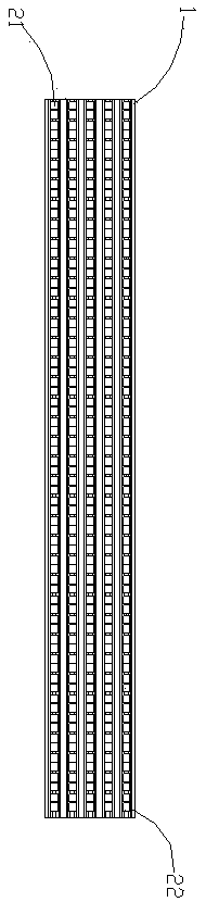
[0025] Such as figure 1 As shown, the unpowered roller conveying platform in this embodiment includes a bracket 1, and a plurality of roller mechanisms arranged on the bracket 1, and the plurality of roller mechanisms are arranged in an array on the bracket. In the embodiment, two roller mechanisms are combined to form a roller mechanism, and 5 rows and 36 columns are formed. There are gaps between rows and columns, forming a matrix in this embodiment. Of course, the arranged multiple roller mechanisms can also be arranged in an array of other styles, such as a curved pattern, so as to meet other needs, such as space setting needs.

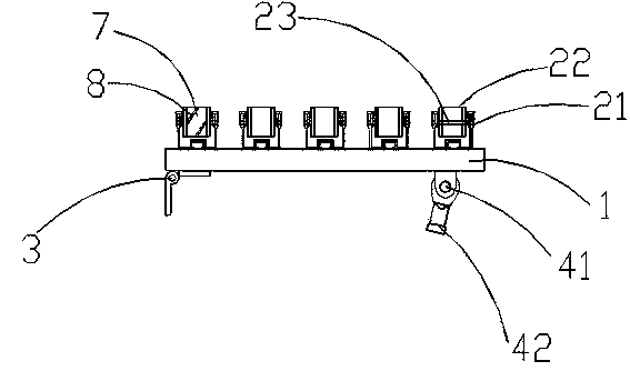
[0026] Such as figure 1 , figure 2 As shown, the above-mentioned bracket 1 includes a roller bracket 22, the above-mentioned roller mechanism includes a roller shaft 23 and a roller 21, the roller bracket 22 is horizontally erected on the bracket 1, and the roller 21 is connected to the roller bracket 22 through the roller shaft 23, The roller...

Embodiment 2

[0030] Others are the same as those described in Embodiment 1, except that the roller bracket 22, as a part of a single roller mechanism, forms a roller mechanism together with the roller shaft 23 and the roller 21, and is then installed on the bracket 1 one by one. In this way, the material for manufacturing the roller bracket 22 can be saved.

Embodiment 3

[0032] Others are the same as those described in Embodiment 1 or 2, except that the rubber skin 7 is not added to the roller 21, but several grooves are directly provided on the roller 21, which can also achieve the purpose of increasing the friction.

[0033] The working principle of the present invention is introduced below:

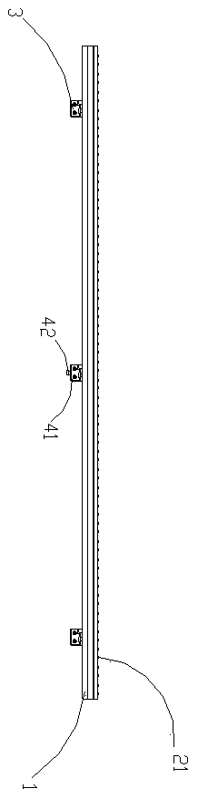
[0034] A number of roller mechanisms including rollers 21 are set on the bracket 1 of the platform, which are arranged on the bracket 1 in an array. Through the rotation of the rollers 21, the traditional belt transmission is replaced by a non-powered form, and the transmission process does not require power. , reduces power consumption and saves cost; the addition of optional rubber skin 7 and groove 8 increases the friction between the roller 21 and the product to be processed, making the roller 21 corrosion-resistant and wear-resistant, and extending the life of the roller 21 Long service life; Cylinder 5 enables the height of the platform to be adj...


PUM


Abstract

The invention discloses an unpowered roller conveying platform which can be detachably connected with a rack. The unpowered roller conveying platform comprises a bracket and a plurality of roller mechanisms arranged on the bracket, and the roller mechanisms are arranged on the bracket in an array type. According to the unpowered roller conveying platform, the platform composed of the bracket and the roller mechanisms is used for replacing a traditional conveying platform, rolling of rollers in the roller mechanisms drives products to be processed to move forwards to achieve the conveying process, power is needless in the conveying process, power consumption is lowered, and cost is saved.

Description

technical field [0001] The invention relates to a conveying device, in particular to an unpowered roller conveying platform. Background technique [0002] In modern manufacturing and processing, in order to replace the traditional manual handling, the conveying platform is generally used to transport the products to be processed to improve the processing efficiency of the products. [0003] In the current conveying platform, such as the conveying platform on the edge grinding machine, the belt conveyor is a widely used conveying device, which is widely used in conveying various solid blocks and powders in agriculture, industrial and mining enterprises and transportation industries. Shaped materials or finished items, which have the advantages of continuity, high efficiency, saving manpower and material resources, etc., but because they need external power to operate, if they need a lot of power, they will also consume a lot of power, especially In the current situation wher...

Claims


Application Information

Patent Timeline
IPC IPC(8): B65G13/04B65G13/12
Inventor 陈永祥姜慧锋
Owner SUZHOU IND ROBOT TECH
Why Eureka
Try Eureka