Travelling wave thermo-acoustic combined cooling heating and power system

A technology of cogeneration of cooling, heating and power, and thermoacoustic refrigerators. It is applied in refrigerators, refrigeration and liquefaction, and gas cycle refrigerators. Combined supply is simple, effective and efficient technical approaches to achieve good heat source adaptability and simplify complexity

Active Publication Date: 2014-06-04
TECHNICAL INST OF PHYSICS & CHEMISTRY - CHINESE ACAD OF SCI
View PDF5 Cites 24 Cited by
  • Summary
  • Abstract
  • Description
  • Claims
  • Application Information

AI Technical Summary

Problems solved by technology

However, due to the too many access points of the refrigerator on the engine loop, the distribution of sound power in the system is extremely complicated, and it is difficult to

Method used


Image

  • Travelling wave thermo-acoustic combined cooling heating and power system
  • Travelling wave thermo-acoustic combined cooling heating and power system
  • Travelling wave thermo-acoustic combined cooling heating and power system

Examples


Embodiment 1

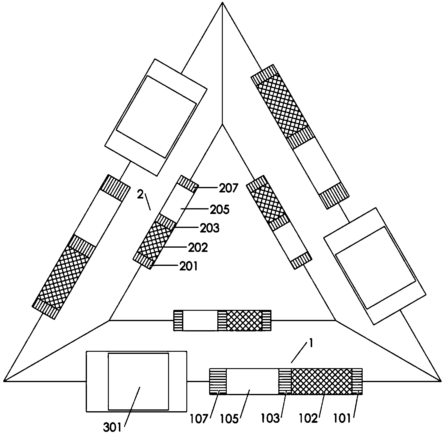
[0030] figure 2 It is a structural schematic diagram of the traveling wave thermoacoustic cogeneration system (embodiment 1) of the present invention. Such as figure 2 As shown, the traveling wave thermoacoustic cogeneration system of this embodiment is composed of three traveling wave thermoacoustic engines 1, three traveling wave thermoacoustic refrigerators 2, three linear motors 3 and a resonance tube 109;

[0031] Each traveling wave thermoacoustic engine 1 includes the engine main cooler 101, the engine regenerator 102, the engine hot end heat exchanger 103, the engine hot end laminar fluidization element 104, the engine heat buffer pipe 105, the engine room temperature end laminar fluidization element 106 and engine subcooler 107;

[0032] Each traveling wave thermoacoustic refrigerator 2 includes a refrigerator main cooler 201, a refrigerator regenerator 202, a refrigerator cold end heat exchanger 203, a refrigerator cold end laminar fluidization element 204, and a...

Embodiment 2

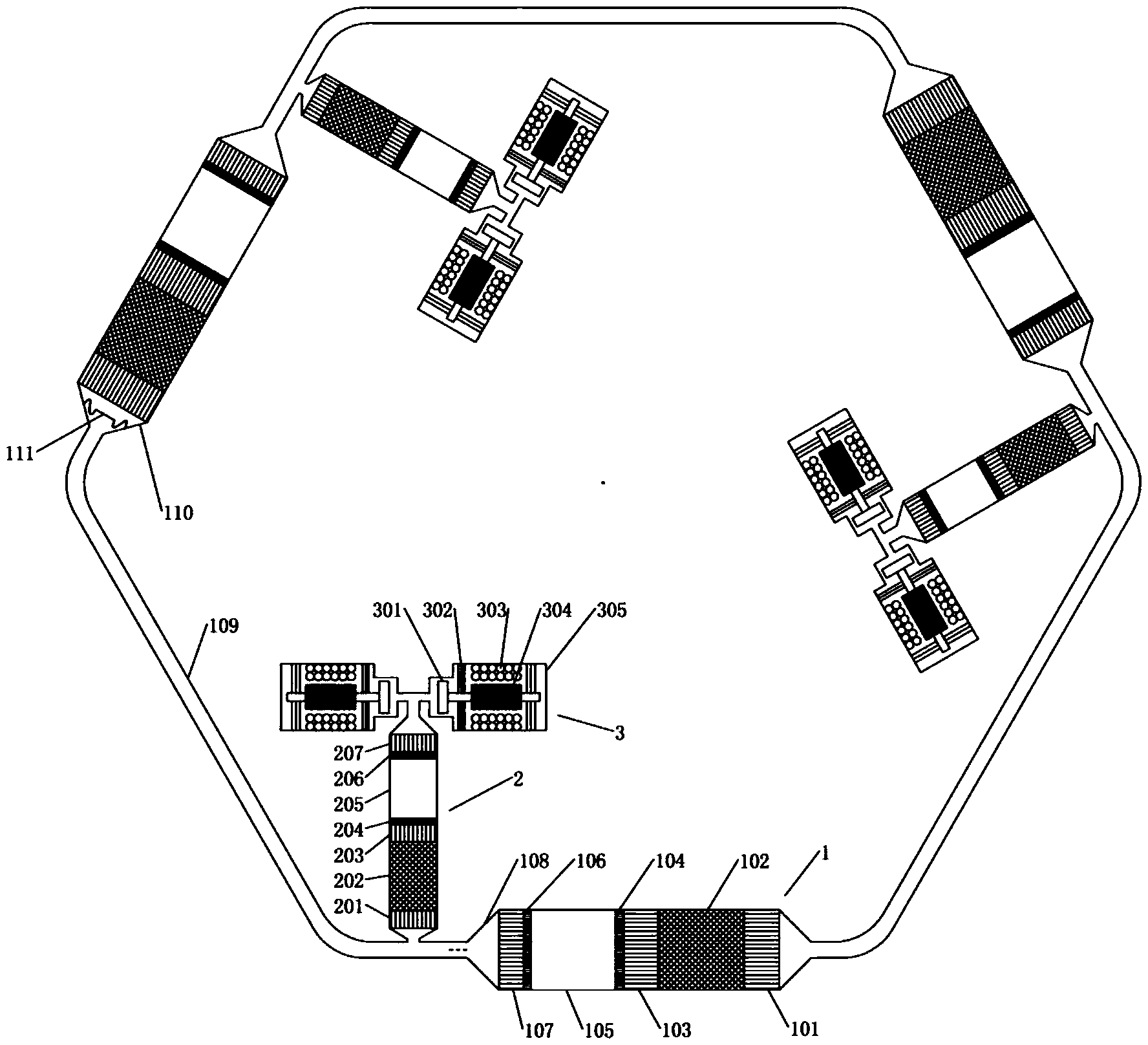
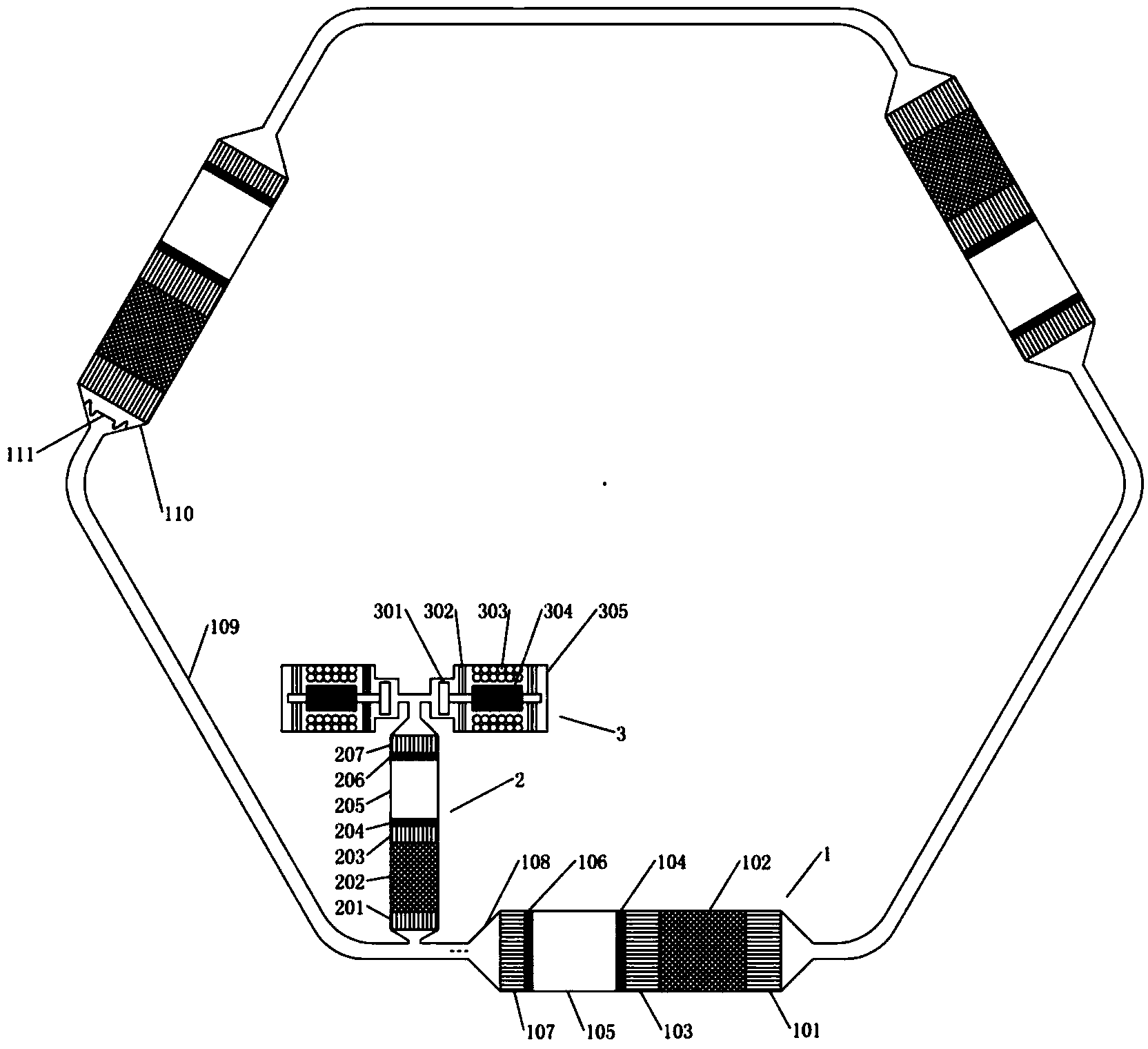
[0039] image 3 It is a structural schematic diagram of the traveling wave thermoacoustic cogeneration system (embodiment 2) of the present invention. Such as image 3 As shown, the traveling wave thermoacoustic cogeneration system of this embodiment consists of three traveling wave thermoacoustic engines 1, one traveling wave thermoacoustic refrigerator 2, one linear motor 3 and a resonance tube 109;

[0040] Each traveling wave thermoacoustic engine 1 includes the engine main cooler 101, the engine regenerator 102, the engine hot end heat exchanger 103, the engine hot end laminar fluidization element 104, the engine heat buffer pipe 105, the engine room temperature end laminar fluidization element 106 and engine subcooler 107;

[0041] In this embodiment, there is only one traveling wave thermoacoustic refrigerator 2, and the traveling wave thermoacoustic refrigerator 2 includes a refrigerator main cooler 201, a refrigerator regenerator 202, and a refrigerator cold end hea...

Embodiment 3

[0050] Figure 4 It is a structural schematic diagram of the traveling wave thermoacoustic cogeneration system (embodiment 3) of the present invention. Such as Figure 4 As shown, this embodiment includes four traveling wave thermoacoustic engines 1, four traveling wave thermoacoustic refrigerators 2, four linear generators 3 and four sections of resonance tubes 109; the four traveling wave thermoacoustic engines 1 The resonant tubes 109 are connected end to end to form a loop circuit; and each resonant tube 109 is bypassed with a traveling wave thermoacoustic refrigerator 2 and a linear generator 3 . In fact, the traveling wave thermoacoustic refrigerator 2 and the linear generator 3 can be respectively bypassed at the end of the resonant tube 109 or at any position on the resonant tube 109 .


PUM


Abstract

The invention relates to a travelling wave thermo-acoustic combined cooling heating and power system which is composed of at least three travelling wave thermo-acoustic engines, at least one travelling wave thermo-acoustic refrigerating machine, a linear generator and resonance units. The travelling wave thermo-acoustic engines are connected in an end-to-end mode through the resonance units to form a loop. One end of the travelling wave thermo-acoustic refrigerating machine is laterally connected to the resonance units, and the other end of the travelling wave thermo-acoustic refrigerating machine is connected with the linear generator. The travelling wave thermo-acoustic combined cooling heating and power system converts heat energy into acoustic power through the travelling wave thermo-acoustic engines, the travelling wave thermo-acoustic refrigerating machine achieves refrigeration through a part of acoustic power, the linear generator converts the acoustic power at an outlet of the travelling wave thermo-acoustic refrigerating machine into electric energy and provides a suitable phase position for the travelling wave thermo-acoustic refrigerating machine, and the performance of the travelling wave thermo-acoustic refrigerating machine is improved. The temperature of cooling water of each cooling machine is increased to be used for life heat supply. Compared with the prior art, the travelling wave thermo-acoustic combined cooling heating and power system can achieve output of cold energy and electric energy at the same time in one device, the systematic complexity is reduced, the reliability is improved, and the travelling wave thermo-acoustic combined cooling heating and power system has the advantages of being high in efficiency, flexible in power and the like, and can be applied to the field of utilization of energy such as solar energy, industrial waste heat and biomass energy.

Description

technical field [0001] The invention relates to a combined cooling, heating and power system, in particular to a traveling wave thermoacoustic combined cooling, heating and power system. Background technique [0002] In many occasions in industrial production and residential life, cooling, heating, and electricity resources are required at the same time. In the field of energy, a distributed combined cooling, heating and power supply scheme was proposed many years ago, which can simultaneously provide electricity, cold energy and heat energy for domestic use. The existing combined cooling, heating and power systems mostly use natural gas or liquid fuel as primary energy, use gas turbines, internal combustion engines or steam turbines to generate electric energy, and then use absorption or adsorption refrigeration to convert the high-temperature waste heat of the above systems into cold energy. The waste heat which is slightly higher than the ambient temperature is used for ...

Claims


Application Information

Patent Timeline
IPC IPC(8): F03G7/00F25B23/00
CPCF25B2309/1426
Inventor 吴张华罗二仓张丽敏陈燕燕戴巍李东辉毕天骄
Owner TECHNICAL INST OF PHYSICS & CHEMISTRY - CHINESE ACAD OF SCI
Why Eureka
Try Eureka