Stress monitoring device and manufacturing method

A technology of stress monitoring and manufacturing method, which is applied in the direction of measuring the change force of the optical properties of the material when it is stressed, and can solve the problem that the tethered stress monitoring device is easily affected by environmental factors, cannot be accurately measured, and cannot be used for fiber grating stress. Real-time monitoring of changes and other issues to achieve the effects of being susceptible to electromagnetic interference, enhancing the ability to resist electromagnetic interference, and enhancing environmental adaptability

Inactive Publication Date: 2014-06-04
8TH RES INST OF CETC
View PDF11 Cites 6 Cited by
  • Summary
  • Abstract
  • Description
  • Claims
  • Application Information

AI Technical Summary

Problems solved by technology

[0006] The purpose of the present invention is to improve a stress monitoring device and solve the technical problem that the fiber grating cannot be used for effective real-time monitoring of stress changes
[0007] Another object of the present invention is to provide a manufacturing method to solve the technical problem that the tethered stress monitoring device for the tethered cables of the floating platform is easily affected by environmental factors and cannot be accurately measured

Method used


Image

  • Stress monitoring device and manufacturing method
  • Stress monitoring device and manufacturing method
  • Stress monitoring device and manufacturing method

Examples


Embodiment Construction

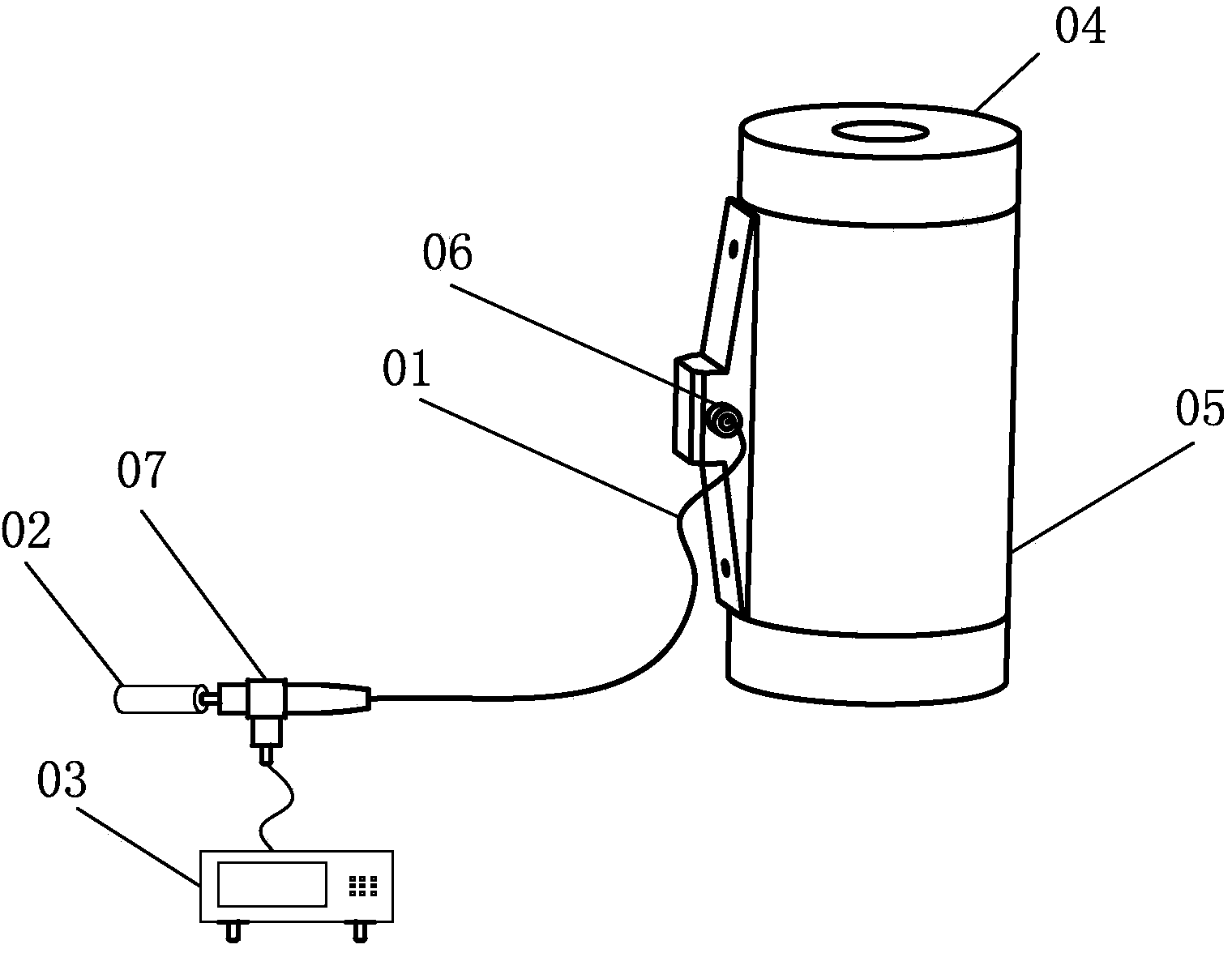
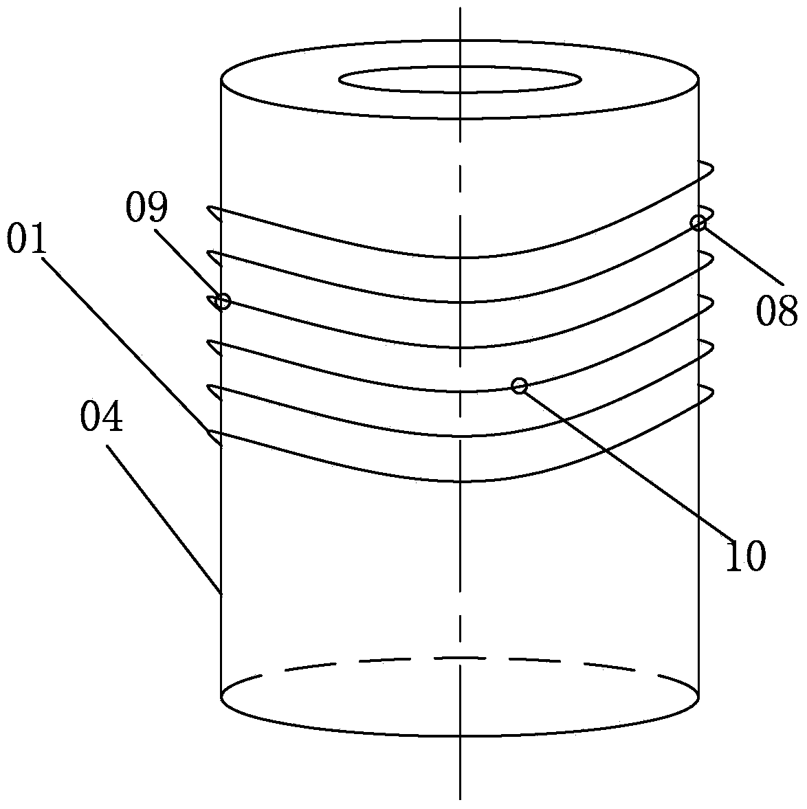
[0033] Such as figure 1 As shown, this embodiment includes a fiber grating, an optical fiber 01, and a strain body (pressure body) 04. On the side wall of the strain body 04, a protective shell 05 covering the side wall is fixedly installed. On the protective shell 05, there are The fiber outlet hole 06 is surrounded by a protective baffle; in the layout space between the protective housing 05 and the side wall of the strain body 04, the first end of the optical fiber 01 is fixed on the side wall of the strain body, along the strain body 04 axial direction, wind the optical fiber 01 on the side wall of the strain body 04 according to a certain winding distance and fix it, install a fiber grating on the optical fiber along the axial direction of the optical fiber 01, and the second end of the optical fiber 01 protrudes out of the protective housing through the fiber outlet hole 06 05, connected to the broadband incident light source 02, and the fiber grating demodulator 03 is c...


PUM

PropertyMeasurementUnit
wavelengthaaaaaaaaaa
lengthaaaaaaaaaa

Abstract

The invention provides a stress monitoring device. The stress monitoring device comprises a fiber bragg grating, an optical fiber and a strain body. A protective shell covering the sidewall is fixedly arranged on the sidewall of the strain body. A fiber outlet hole is formed in the protective shell. A protective baffle is arranged around the fiber outlet hole. In a layout space between the protective shell and the sidewall of the strain body, the first end of the optical fiber is fixed to the sidewall of the strain body, and the optical fiber is wound and fixed to the sidewall of the strain body according to a certain winding distance in the axial direction of the strain body. The fiber bragg grating is arranged on the optical fiber in the axial direction of the optical fiber. The second end of the optical fiber extends out of the protective shell through the fiber outlet hole and is connected with a wideband incident light source. A fiber bragg grating demodulation instrument is connected with the second end of the optical fiber through an optical coupler. The stress monitoring device can overcome the defects that an existing stress monitoring device is prone to electromagnetic interference, large in temperature excursion and poor in environmental adaptability. The invention further provides a manufacturing method.

Description

technical field [0001] The invention relates to a measuring device and method, in particular to a monitoring device and method for tethering stress. Background technique [0002] Most of the current floating platforms use mooring cables to connect to the anchoring vehicles on the ground to complete the mooring. The cables and optical cables included in the mooring cables are respectively responsible for providing power protection from the ground to the floating platform, and providing uplink and downlink transmission of control signals. When the floating platform is working in the air, once the tethering force of the tethered cables drops, the floating platform will break free from the shackles of the cables, resulting in serious accidents such as out-of-control damage to the sphere and casualties. Therefore, real-time online monitoring of its mooring stress is necessary to ensure the safety of the floating platform. [0003] Today, piezoelectric stress sensors are used be...

Claims


Application Information

Patent Timeline
Patent Type & Authority Applications(China)
IPC IPC(8): G01L1/24
Inventor 陆兆辉
Owner 8TH RES INST OF CETC
Why Eureka
Try Eureka