Optical sheet illumination microscopic method and device based on differential
What is AI technical title?
AI technical title is built by Patsnap AI team. It summarizes the technical point description of the patent document.
A light sheet and differential technology, applied in the field of light sheet illumination microscopy, to achieve the effects of ensuring imaging depth, convenient data processing, and simple device structure
Active Publication Date: 2014-06-04
ZHEJIANG UNIV
View PDF6 Cites 18 Cited by
Summary
Abstract
Description
Claims
Application Information
AI Technical Summary
This helps you quickly interpret patents by identifying the three key elements:
Problems solved by technology
Method used
Benefits of technology
Problems solved by technology
[0004] However, because the resolution of the microscope is related to the numerical aperture of the objective lens, the larger the numerical aperture, the smaller the spot focused on the sample surface, and the higher the resolution of the microscope. At the same time, the imaging depth is inversely proportional to the numerical aperture. The larger the imaging depth, the smaller the imaging depth, so the traditional light-sheet illumination microscope can only observe the living dynamics of animals and plants at the subcellular level, and cannot achieve super-resolution microscopic imaging while ensuring the imaging depth
Method used
Image
Click on the blue label to locate the original text in one second.
Reading with bidirectional positioning of images and text.
Examples
Embodiment 1
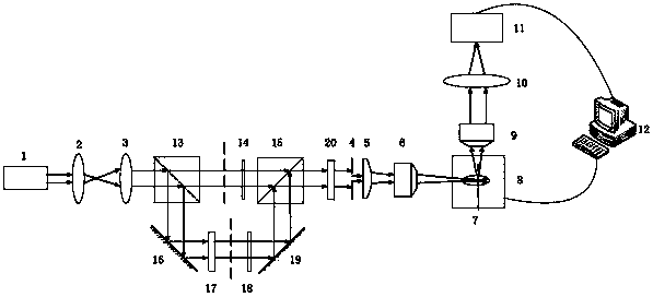
[0035] like figure 2 As shown, a shutter-controlled light-sheet illumination microdevice for fluorescent samples, including a laser 1, a first lens 2, a second lens 3, a first polarizing beam splitter 13, a first shutter 14, a second Two polarization beam splitter 15, quarter wave plate 20, slit 4, cylindrical mirror 5, first objective lens 6, first reflection mirror 16, phase plate 17, second shutter 18, second reflection mirror 19, sample 7. Nano translation stage 8, second objective lens 9, third lens 10, detector 11 and computer 12.
[0036] use figure 2 The shown setup implements a differential-based light-sheet illumination microscopy method for samples, and the procedure is as follows:
[0037] (1) The laser 1 emits illumination light, which is expanded by the first lens 2 and the second lens 3;
[0038] (2) The expanded illumination light is divided into two orthogonal linearly polarized beams by the first polarizing beam splitter 13, in which the vertically polar...
Embodiment 2
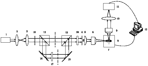
[0044] Such as image 3 As shown, a differential-based light sheet illumination microdevice controlled by a liquid crystallight valve for fluorescent samples includes a laser 1, a first lens 2, a second lens 3, a liquid crystallight valve 21, and a first polarizing beam splitter 13 , second polarizing beam splitter 15, quarter wave plate 20, slit 4, cylindrical mirror 5, first objective lens 6, first mirror 16, phase plate 17, second mirror 19, sample 7, nano Translation stage 8, second objective lens 9, third lens 10, detector 11 and computer 12.
[0045] use image 3 The shown setup implements a differential-based light-sheet illumination microscopy method for samples, and the procedure is as follows:
[0046] (1) The laser 1 emits illumination light, which is expanded by the first lens 2 and the second lens 3;
[0047] (2) First, use the liquid crystallight valve 21 to convert the beam-expanded illumination light into parallel polarized light (p light), and the light ...
PUM
Abstract
The invention discloses an optical sheet illumination microscopic method based on differential; the method comprises the following steps: 1, a lighting beam after beam expanding is converted into parallel polarized light and vertical polarized light; 2, the parallel polarized light is individually used, the parallel polarized light with a light spot as a solid center is regarded as a first illumination light converted to a first circular polarized illumination light, the first circular polarized illumination light is focused to a surface of a fluorescence sample through a focusing module, and the fluorescence emitted by the fluorescence sample is collected to obtain a first photo; 3, the vertical polarized light is individually used and modulated into a second illumination light having a hollow light spot, the second illumination light is converted into a second circular polarized illumination light and focused to a surface of the fluorescence sample through the focusing module, and the fluorescence emitted by the fluorescence sample is collected to obtain a second photo; 4, a computer carries out difference treatment for the two photos in the step 2and the step 3, thereby completing scanning of the sample. The invention also discloses an optical sheet illumination microscopic device based on differential.
Description
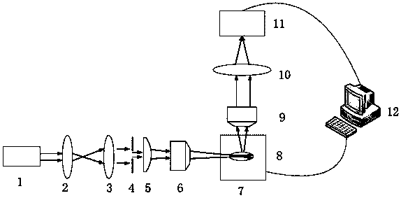
technical field [0001] The invention belongs to the field of light sheet illumination microscopy, in particular to a method and device for light sheet illumination microscopy based on difference. Background technique [0002] Light sheet illumination microscopy uses a layer of light beam to excite the fluorescent sample from the side, and the fluorescent light is received by the detector in the vertical direction of the incident illumination light path to realize imaging. By moving the sample, the incident light path excites different planes, and the excitation beam can be incident on the sample from left and right directions, and the angle of the beam can be changed. Using the light sheet illumination technology, we can easily obtain the image of the whole tissue without slicing the sample. 3D images. Since the plane of excitation of the sample is the imaging plane, photobleaching and optical damage can be minimized. Therefore, the light sheet illumination microscope has ...
Claims
Application Information
Patent Timeline
Application Date:The date an application was filed.
Publication Date:The date a patent or application was officially published.
First Publication Date:The earliest publication date of a patent with the same application number.
Issue Date:Publication date of the patent grant document.
PCT Entry Date:The Entry date of PCT National Phase.
Estimated Expiry Date:The statutory expiry date of a patent right according to the Patent Law, and it is the longest term of protection that the patent right can achieve without the termination of the patent right due to other reasons(Term extension factor has been taken into account ).
Invalid Date:Actual expiry date is based on effective date or publication date of legal transaction data of invalid patent.

