
Magnetic head supporting encryption of magnetic card

A magnetic head and magnetic card technology, which is applied in the field of magnetic heads, can solve the problems that magnetic heads cannot be kept secret and obtained improperly, and achieve the effects of keeping information confidential, solving installation problems, and avoiding information leakage

Inactive Publication Date: 2014-06-04
SUZHOUSRK ELECTRO MAGNETIC TECH
View PDF6 Cites 0 Cited by
  • Summary
  • Abstract
  • Description
  • Claims
  • Application Information

AI Technical Summary

Problems solved by technology

[0002] Patent No. 200810086843.2 discloses a magnetic head for reading card data of a credit card authentication terminal and a magnetic head that cannot illegally obtain card data from a signal line derived from the magnetic head. Inside the case, a wire frame on which the electric wires are wound is provided, and a through hole is provided on the surface of the shielding case opposite to the opening, so that the core member whose end protrudes from the wire frame is exposed from the through hole to the outside of the shielding case. , set the lead pins connected with the winding wires of the wire frame, fill the resin into the hollow core in the shielding case to form a magnetic head, set the lead pins in the filled resin inside the shielding case, and connect the flexible circuit board to the lead pins One end of the flexible circuit board is led out from the opening to the outside. The two lead pins of each coil are arranged separately, and the user can easily read the signal on the magnetic head pin, so that the magnetic head cannot achieve confidentiality. effect

Method used


Image

  • Magnetic head supporting encryption of magnetic card
  • Magnetic head supporting encryption of magnetic card
  • Magnetic head supporting encryption of magnetic card

Examples


Embodiment 1

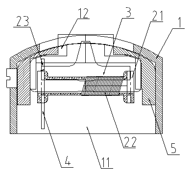
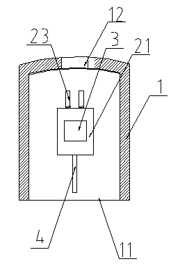
[0020] see figure 1 with figure 2 , as shown in the legend therein, a magnetic head supporting magnetic card encryption includes a magnetic head housing 1, a coil bobbin 21 arranged in the magnetic head housing 1, a coil 22 wound on the coil bobbin 21 and snapped on Two chips 3 in the axial cavity of the coil bobbin 21, the magnetic head housing 1 on both sides of the coil bobbin 21 are respectively provided with an open portion 11 and a through hole 12; the chip 3 protrudes from the through hole 12, and the surface of the coil bobbin 21 is provided with There are two lead pins 23 , and the lead pins 23 are arranged at the same end of the coil frame 21 ; the ends of the coil 22 are wound on the lead pins 23 .

[0021] The lead pins 23 are accommodated in the inner cavity of the magnetic head casing 1 .

[0022] The lead pins 23 are disposed on the bobbin 21 on the side of the through hole 12 of the magnetic head housing 1 .

[0023] An encryption chip (not shown in the fi...

Embodiment 2

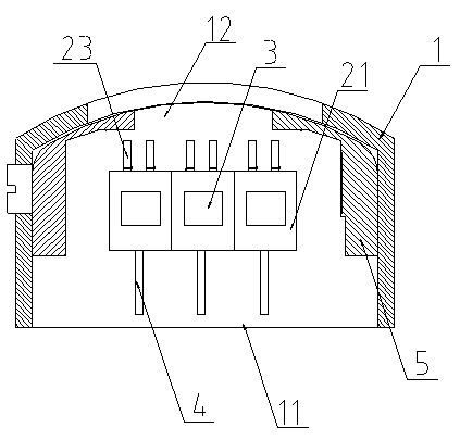
[0029] see figure 1 with image 3 , as shown in the legend therein, the rest are the same as the first embodiment, the difference is that a magnetic head supporting magnetic card encryption includes a magnetic head housing 1, three coil bobbins 21 arranged in the magnetic head housing 1 , three coils 22 wound on the bobbin 21 and two chips 3 engaged in the axial cavity of each bobbin 21, the magnetic head housing 1 on both sides of the bobbin 21 is respectively provided with an opening 11 and A through hole 12; the chip 3 protrudes from the through hole 12, and two lead pins 23 are arranged on the surface of each coil bobbin 21, and the lead pins 23 are arranged at the same end of each coil bobbin 21; the ends of the coil 22 are wound around the lead pins 23 on.

[0030] The lead pins 23 are accommodated in the inner cavity of the magnetic head housing 1 .

[0031] The lead pins 23 are disposed on the bobbin 21 on the side of the through hole 12 of the magnetic head housing...


PUM


Abstract

The invention discloses a magnetic head supporting encryption of a magnetic card. The magnetic head comprises a magnetic head shell, a coil framework arranged inside the magnetic head shell, a coil wound around the coil framework, and chips clamped in an axial cavity of the coil framework, wherein an open part and a through hole are formed in the parts, located on the two sides of the coil framework, of the magnetic head shell respectively, the chips protrude out of the through hole, terminal pins are arranged on the surface of the coil framework and are located at the same end of the coil framework, and the ends of the coil are wound around the terminal pins. Due to the fact that the terminal pins are arranged at the same end of the coil framework, larger space is provided for the magnetic head shell, problems existing in installation of encrypting and decoding chips are solved, and meanwhile, the problem of the magnetic head wire open circuit caused by miniaturization of the magnetic head is solved.

Description

technical field [0001] The invention relates to a magnetic head, in particular to a magnetic head supporting magnetic card encryption. Background technique [0002] Patent No. 200810086843.2 discloses a magnetic head for reading card data of a credit card authentication terminal and a magnetic head that cannot illegally obtain card data from a signal line derived from the magnetic head. Inside the case, a wire rack on which the wires are wound is provided, and a through hole is provided on the surface of the shielding case opposite to the opening, so that the core member protruding from the wire rack at one end is exposed from the through hole to the outside of the shielding case. , set the lead pins connected with the winding wires of the wire frame, fill the resin into the hollow core in the shielding case to form a magnetic head, set the lead pins in the filled resin inside the shielding case, and connect the flexible circuit board to the lead pins One end of the flexibl...

Claims


Application Information

Patent Timeline
IPC IPC(8): G07F7/10
Inventor 张虎臣沈伟林毛维贤
Owner SUZHOUSRK ELECTRO MAGNETIC TECH
Features
  • Generate Ideas
  • Intellectual Property
  • Life Sciences
  • Materials
  • Tech Scout
  • Unparalleled Data Quality
  • Higher Quality Content
  • 60% Fewer Hallucinations
Learn More