Light-emitting keyboard

A technology of light-emitting keyboards and light-emitting components, which is applied in the direction of electrical components, electric switches, circuits, etc., can solve the problems of electrical conduction, the inability to implement light-emitting keyboards, and the inability to meet appearance demands, and achieve the effect of improving use efficiency

Inactive Publication Date: 2014-06-04
PRIMAX ELECTRONICS LTD
View PDF7 Cites 55 Cited by
  • Summary
  • Abstract
  • Description
  • Claims
  • Application Information

AI Technical Summary

Problems solved by technology

[0009] 1. Although the reflector 11 can assist the light beams scattered downward by multiple light guide points 121 to reflect upward, the material of the reflector 11 of the existing light-emitting keyboard 1 can still allow a little light beam to penetrate, so part of it is made up of multiple light guides. The light beam scattered downward by point 121 will penetrate the reflector 11 and cause the loss of light quantity
[0010] 2. Although the light beam can be diffused to the entire light guide plate 12 when it enters the light guide plate 12, part of the light beam has been reflected out of the light guide plate 12 due to the light guide point 121 that is closer to the side light-emitting element 16, so that the light guide plate 12 The amount of light in the area farther from the side light emitting element 16 is not as sufficient as the area closer to the side light emitting element 16
[0011] 3. Since the scissor-type connecting element 153 has a relatively long operation stroke, the light-emitting keyboard 1 must have enough space to enable the scissor-type connecting element 153 to operate normally. However, the thickness of the light-emitting keyboard 1 cannot be effectively reduced, so that Unable to meet the appearance demands of today's electronic products towards light, thin and short development
[0012] From the description of the above first and second points, it can be seen that although the existing luminous keyboard 1 makes the plurality of keys 15 emit light through the cooperation of the side-type light-emitting elements 16 and the light guide plate 12, the light use efficiency is not good.
Based on this, under the thinking of how to improve the efficiency of light use, try to replace the side-type light-emitting element 16 with a direct-type light-emitting element, and arrange the direct-type light-emitting element under the key 15 to directly provide light beams to the key 15, thereby Better light use efficiency is obtained; however, in this approach, the direct-type light-emitting element is located in the moving stroke of the key 15, so the user cannot press the keycap 151 to make the corresponding membrane switch 144 reach the electrical level. Therefore, the method of replacing the side-type light-emitting element 16 with a direct-type light-emitting element and directly providing light beams to the keys 15 cannot be implemented on the existing light-emitting keyboard 1
[0013] Furthermore, in view of the defects described in the third point above, a capacitive sensing keyboard has been proposed, which changes the electric field of a corresponding capacitive switch in the circuit board of the keyboard when the keycap is pressed down. And make the circuit board generate and output a corresponding button signal; Wherein, because the capacitive sensing keyboard does not necessarily need to use related components such as scissor-type connection elements, the overall thickness of the capacitive sensing keyboard can be effectively reduced; However, there is no such thing as yet. A capacitive-sensing keyboard with a luminous effect was proposed, so in a low-light environment, users may not be able to see clearly the numbers and characters marked on the keys on the capacitive-sensing keyboard, resulting in difficulty in operation or impaired vision

Method used


Image

  • Light-emitting keyboard
  • Light-emitting keyboard
  • Light-emitting keyboard

Examples


Embodiment Construction

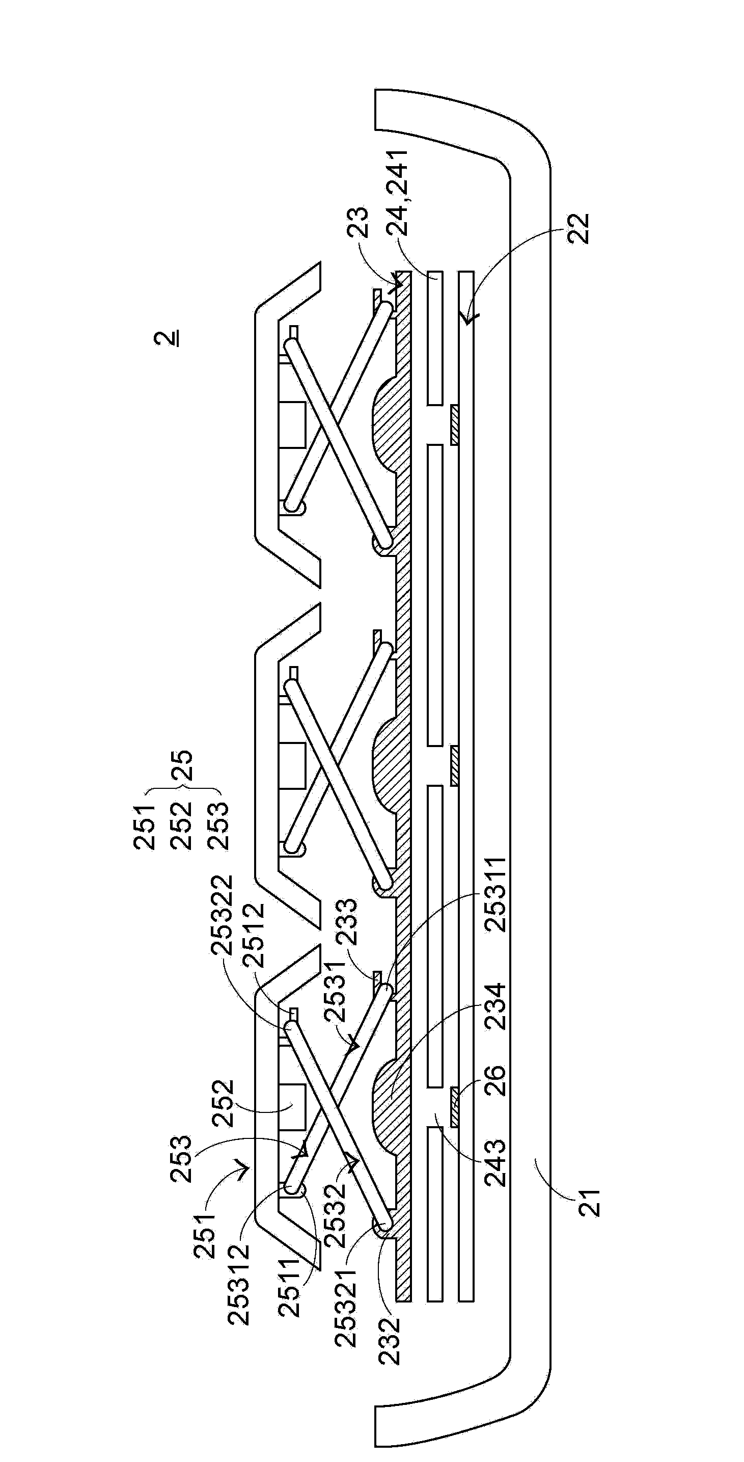
[0117] see image 3 and Figure 4 , image 3 It is a side view of the structure of the luminous keyboard in the first preferred embodiment of the present invention, Figure 4 for image 3 The structure diagram of the sensing circuit layer and the driving circuit board of the light-emitting keyboard shown. The luminous keyboard 2 includes a base 21, a light-emitting element driving circuit board 22, a sensing circuit layer 24, a light-transmitting support plate 23, and a plurality of keys 25 in sequence from bottom to top, and the luminous keyboard 2 also includes buttons corresponding to the plurality of keys 25. A plurality of direct-type light-emitting elements 26; wherein, the base 21 is used to carry a light-emitting element driving circuit board 22, a sensing circuit layer 24, a light-transmitting support plate 23, a plurality of buttons 25, and a plurality of direct-type light-emitting elements 26, and the light-emitting element drives A light-emitting element drivin...


PUM


Abstract

The invention provides a light-emitting keyboard comprising multiple direct illumination-type light-emitting elements, an induction circuit layer, multiple keys and a light-transmitting supporting plate. When the keys are close to the induction circuit layer, the induction circuit layer correspondingly generates a non-contact type key signal. Besides, each direct illumination-type light-emitting element is corresponding to one key and arranged below the corresponding key. The light-transmitting supporting plate is arranged between the multiple direct illumination-type light-emitting elements and the multiple keys. Light beams of each direct illumination-type light-emitting element penetrate through the light-transmitting supporting plate and then are projected to the corresponding key. Use efficiency of light can be effectively enhanced by the light-emitting keyboard.

Description

technical field [0001] The invention relates to a keyboard, in particular to a keyboard with a light-emitting function. Background technique [0002] In recent years, due to the rapid development of the information industry, many users may use portable information devices in different environments, such as notebook computers, mobile phones or personal digital assistants. In a low-light environment, users may not be able to clearly see the numbers and characters marked on the keyboard keys, thus causing difficulties in operation, and in severe cases, may even cause vision loss due to barely recognizing the key marks. Therefore, the launch of the luminous keyboard can improve the inconvenience of the user using the keyboard in places with insufficient light. What's more, through different lighting configurations, the information device using the lighting keyboard can be made to look more beautiful, thereby increasing its sales. [0003] see figure 1 , which is a structural ...

Claims


Application Information

Patent Timeline
Patent Type & Authority Applications(China)
IPC IPC(8): H01H13/83
Inventor 陈仲渊
Owner PRIMAX ELECTRONICS LTD
Why Eureka
Try Eureka