Side shifting type spraying mechanism and method for internal coating of anticorrosion steel pipe
A technology of anti-corrosion steel pipe and spraying mechanism, which is applied in the direction of coating, liquid coating device on the surface, etc., can solve the problems of inconvenient operation, large floor area, and low utilization rate of the plant, so as to save space in the length direction and improve The utilization rate of the factory area and the effect of reducing the work schedule
- Summary
- Abstract
- Description
- Claims
- Application Information
AI Technical Summary
Problems solved by technology
Method used
Image
Examples
Embodiment 1
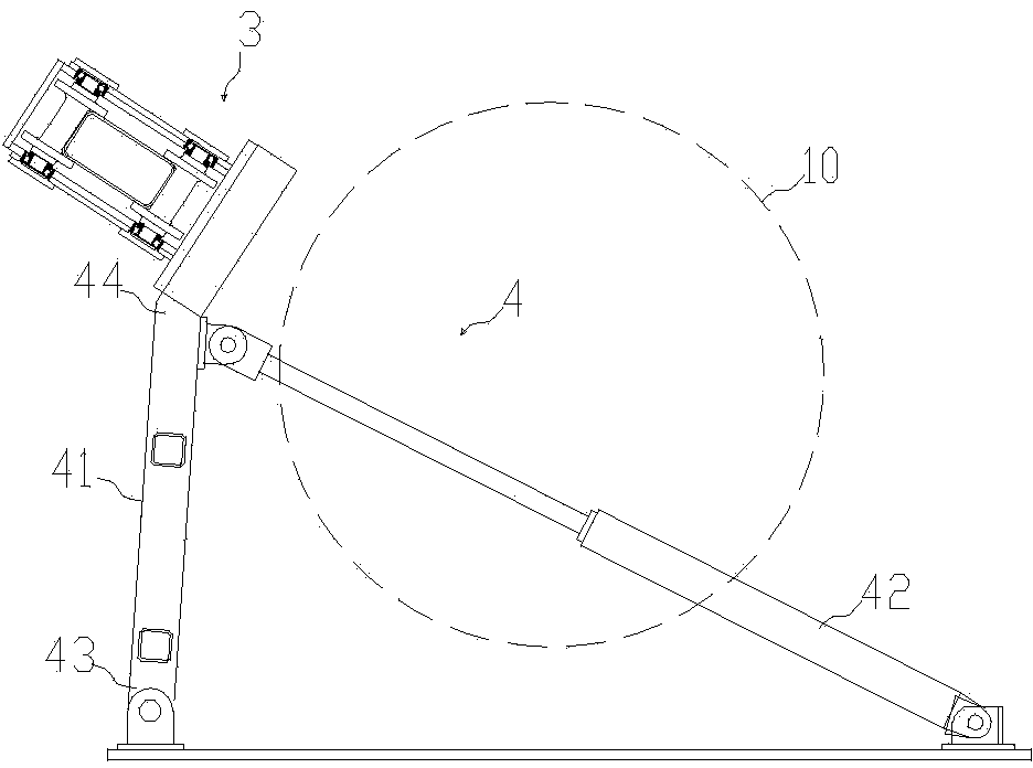
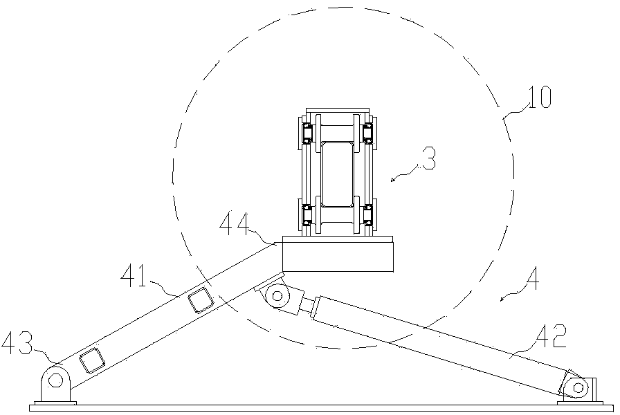
[0040] The side-moving spraying mechanism for the inner coating of the anti-corrosion steel pipe consists of an inner spraying rod 1 that can move along a parallel axis a, a spray gun assembly 2 located at the front end of the inner spraying rod 1, a support assembly 3 located at the rear end of the inner spraying rod 1, and a The spraying rod 1 is composed of a first displacement device 4 that moves sideways to the axis a at the pre-coating station parallel to the axis a, and a second displacement device 5 connected to the inner spraying rod 1 . The axis a coincides with the centerline of the steel pipe 10 .
[0041] Such as figure 2 , image 3 As shown, the first displacement device 4 includes a lateral displacement assembly and a drive assembly 42 for driving the lateral displacement assembly. The side shift assembly is an adjustment rod 41, which includes a fixed end 43 for positioning and a free end 44 connected to the drive assembly 42; the drive assembly 42 is a hydr...
Embodiment 2
[0056] The difference between the second embodiment and the first embodiment is that the structure of the first displacement device is different. In the second embodiment, the displacement of the inner spraying rod 1 is an up and down displacement relative to the axis a.
[0057] The first displacement device 4 includes a lateral displacement assembly and a driving assembly 42 for driving the lateral displacement assembly. Such as Figure 8 , Figure 9 As shown, the side shift assembly is two adjusting rods 41 that are crossed in an X shape and are movably connected. The lower ends of the two adjusting rods 41 are connected to a fixing member 45, and the upper ends are connected to a lifting member 46; The drive assembly 42 is a hydraulic cylinder; the two adjusting rods 41 can be opened or closed under the drive of the hydraulic cylinder, and the lifting member 46 rises and falls accordingly, and the above-mentioned support assembly 3 is connected to the lifting member 46, ...
PUM
 Abstract
Description
Claims
Application Information
 - R&D
- Intellectual Property
- Life Sciences
- Materials
- Tech Scout
- Unparalleled Data Quality
- Higher Quality Content
- 60% Fewer Hallucinations
Browse by: Latest US Patents, China's latest patents, Technical Efficacy Thesaurus, Application Domain, Technology Topic, Popular Technical Reports.
© 2025 PatSnap. All rights reserved.Legal|Privacy policy|Modern Slavery Act Transparency Statement|Sitemap|About US| Contact US: help@patsnap.com


