
Quenching cooling monitoring system

A monitoring system and control system technology, which is applied in heat treatment process control, heat treatment equipment, manufacturing tools, etc., can solve problems such as defective products, economic losses, and wear of cooling motors

Active Publication Date: 2014-06-11
东莞市禾盛金属科技有限公司 +2
View PDF4 Cites 7 Cited by
  • Summary
  • Abstract
  • Description
  • Claims
  • Application Information

AI Technical Summary

Problems solved by technology

This change may come from: 1) fouling of the heat exchanger, which reduces the heat exchange efficiency; 2) the wear of the water pump during long-term use reduces the cooling capacity; 3) deformation of the cooling fan blades reduces the cooling capacity; 4) The cooling motor wears out, resulting in reduced cooling capacity, etc.
This change is very likely to be gradual (and sometimes sudden), and the external manifestations are not obvious, so it is difficult to detect in time
In the production process where the cooling performance gradually decreases, there is a possibility of defective products
This kind of defective product may be difficult to find in the usual sampling inspection process, and it may take a long time to find out when the cooling characteristics have sufficiently deteriorated.
By this time, there may have been a considerable number of defective products, which may have constituted a major economic loss

Method used

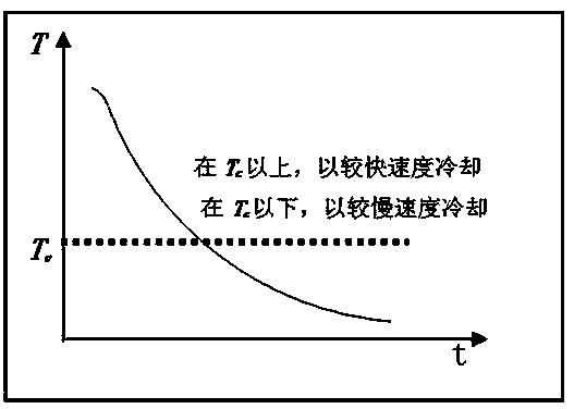
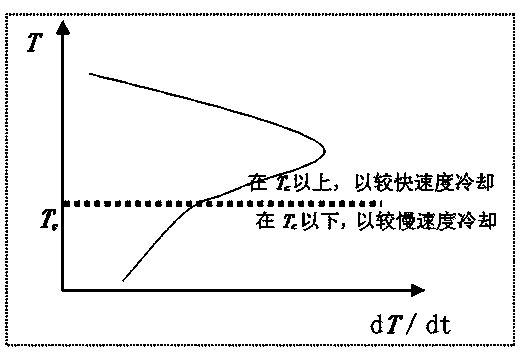

Image

  • Quenching cooling monitoring system
  • Quenching cooling monitoring system
  • Quenching cooling monitoring system

Examples


Embodiment Construction

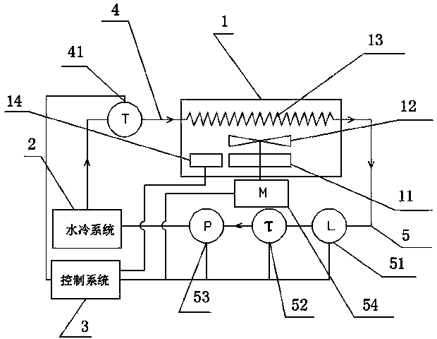
[0053] In this embodiment, refer to image 3 As shown, the quenching cooling monitoring system includes a water cooling system 2, a heat exchange system 1 and a control system 3, as well as a cold conveying pipe 4 and a heat conveying pipe 5 arranged in a clockwise layout between the water cooling system 2 and the heat exchange system 1, And the cold end thermometer 41 arranged on the cold conveying pipe 4 for detecting the temperature of the cooling liquid, and the flow meter 51, the hot end thermometer 52 and the water pump 53 arranged in a clockwise layout on the hot conveying pipe 5; the described The heat exchange system 1 is provided with an air pressure gauge 14, a convection fan blade 12 and a heat exchanger 13. The convection fan blade 12 blows the air flow to blow the heat on the workpiece 11 to the heat exchanger 13, and the cooling liquid pushes the heat exchanger 13. The heat is absorbed and taken away; the heat exchange system 1 is provided with a convection fan ...


PUM


Abstract

The invention discloses a quenching cooling monitoring system, comprising a water-cooling system, a heat exchange system, a control system, a cold delivery pipe, a heat delivery pipe, a cold end temperature measuring meter, a flow meter, a hot end temperature measuring meter and a water pump, wherein a plenum gauge is arranged inside the heat exchange system; the monitoring system calculates and records according to the real-time measurement information fed back by the cold end temperature measuring meter, the flow meter, the hot end temperature measuring meter and the plenum gauge. Thus, the online monitoring function of the cooling process is achieved; the monitoring data can be used as a foundation for quality judgment; the monitoring system also can emit a corresponding real-time control signal according to the actual cooling condition according to the preset and the actual cooling condition; the rotating speeds of a convection fan blade motor and a water-cooling system motor and gas pressure inside the heat exchange system are controlled to achieve the target of adjusting the cooling speed. The implementation of the quenching cooling monitoring system also can be used as equipment for detecting the cooling capacity of a vacuum furnace at regular intervals, and also can be used as an effective tool for a research design of the vacuum furnace. Thus, the energy-efficient target is achieved, and the trend of development of the technology at present is accorded.

Description

technical field [0001] The invention relates to a quenching and cooling monitoring system, in particular to a quenching and cooling monitoring system which combines a thermometer, a flowmeter and an aeration pressure gauge to perform precise detection and control and to accurately evaluate the efficiency of the cooling system. Background technique [0002] For gas quenching vacuum furnaces, the main factor that determines the cooling capacity (speed) is the heat transfer efficiency of the heat exchanger. The factors that affect the heat exchange efficiency are: the cooling water flow, the gas pressure in the cooling chamber (quenching chamber) and the rotational speed of the cooling fan blades. The cooling capacity of the gas quenching vacuum furnace determines its production capacity (applicable workpiece size, material type, etc.), and the stability of the cooling capacity determines the quality stability during batch production (repeated production of the same part on a l...

Claims


Application Information

Patent Timeline
Patent Type & Authority Applications(China)
IPC IPC(8): C21D11/00C21D1/18
Inventor 刘小阳
Owner 东莞市禾盛金属科技有限公司
Learn More