Rail Lifting Device of Mobile Rail Flash Welding Machine

A flash welding machine and mobile technology, which is applied in the direction of track, track laying, track maintenance, etc., can solve the problems that the outer dimension of the welding machine does not meet the requirements of use, the rail welding operation cannot be performed, and the process of padding rollers is complicated, etc. The effect of restricting long rails, simple structure, and large rail lifting load

Active Publication Date: 2015-12-23
CHANGZHOU RUITAI ENG MASCH CO LTD +1
View PDF5 Cites 0 Cited by
  • Summary
  • Abstract
  • Description
  • Claims
  • Application Information

AI Technical Summary

Problems solved by technology

The process of padding rollers at both ends of the welded joint of the rail is complicated, the workload is heavy, and the construction efficiency is extremely low
In addition, when welding rail repairs in subway tunnels, the available welding space in the tunnels is quite narrow, and the overall dimensions of general welding machines basically do not meet the requirements for use.
It is more inconvenient to use the traditional way of raising the rails at both ends of the welded joint with rollers, and even the rail welding operation cannot be performed

Method used


Image

  • Rail Lifting Device of Mobile Rail Flash Welding Machine
  • Rail Lifting Device of Mobile Rail Flash Welding Machine
  • Rail Lifting Device of Mobile Rail Flash Welding Machine

Examples


Embodiment Construction

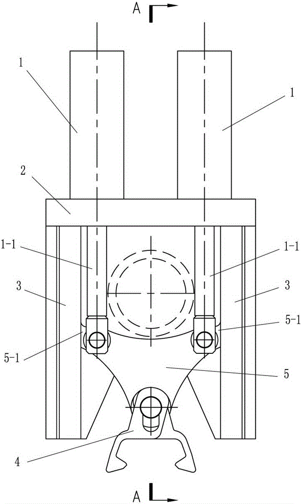
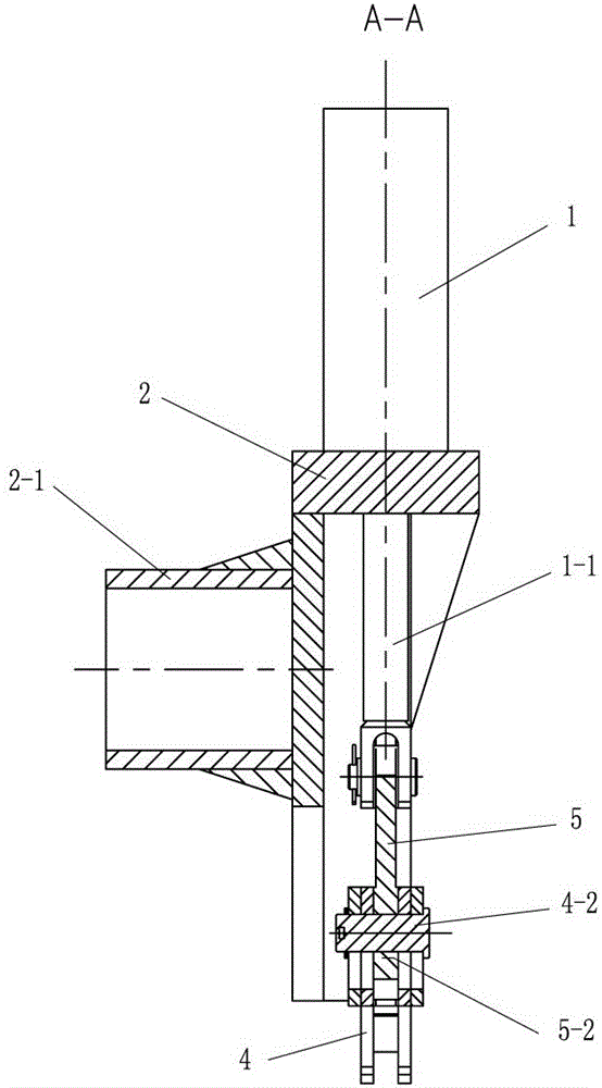
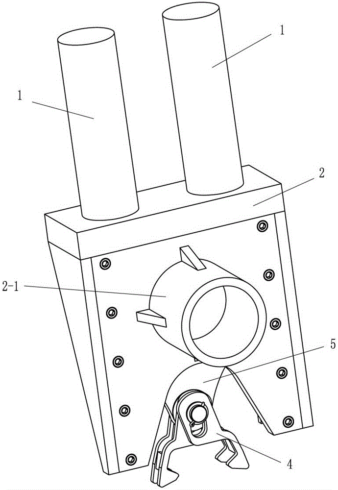
[0017] Such as figure 1 , 2 , 3, 4, and 5, the rail lifting device of a mobile rail flash welder of the present invention includes a clamp 4, and also includes a lifting cylinder 1, a mounting bracket 2, a guide rail 3 and a lifting member 5, and the lifting cylinder 1 is installed on the mounting bracket 2, the clamp 4 is connected with the piston rod 1-1 of the lifting cylinder 1 through the lifting piece 5, the guide rail 3 is installed on the mounting bracket 2, and the lifting piece 5 is slidingly matched with the guide rail 3.

[0018] Such as figure 1 , 2 , 4, the lift cylinder 1 has two, and the piston rods 1-1 of the two lift cylinders 1 are jointly connected to the upper end of the lift piece 5, and both sides of the lift piece 5 have sliding parts 5-1, and the lift piece 5 The lower end of the lower end is connected to the fixture 4, and both sides of the mounting bracket 2 are provided with guide rails 3, and the sliding part 5-1 of the lifting member 5 is slida...


PUM


Abstract

The invention discloses a rail lifting device for a movable steel rail flash welding machine, which comprises a fixture, lifting oil cylinders, a mounting bracket, guide rails and a lifting part, wherein the lifting oil cylinders are arranged on the mounting bracket; the fixture is assembled and connected with piston rods of the lifting oil cylinders by a lifting part; the guide rails are arranged on the mounting bracket; and the lifting part is in sliding fit with the guide rails. The rail lifting device is convenient to carry out rail lifting; labor intensity of a constructor is greatly reduced; construction efficiency is high; and the rail lifting device also has the characteristics of simple structure, light weight, flexibility for operation, high rail lifting load, capability of being used for lifting up an unlimited long rail string, convenience for assembling and disassembling and the like.

Description

technical field [0001] The invention relates to flash butt welding equipment, in particular to a rail lifting device of a mobile rail flash welding machine. Background technique [0002] At present, when using a mobile rail flash welding machine for online or offline welding, the rails at both ends of the welded joint must be raised with rollers so that the welder can clamp and weld the rails to be welded. The process of padding rollers at both ends of the welded joint of the rail is complicated, the workload is large, and the construction efficiency is extremely low. In addition, when welding rail repairs in subway tunnels, the available welding space in the tunnels is quite narrow, and the overall dimensions of general welding machines basically do not meet the requirements for use. It is more inconvenient to use the traditional way of raising the rails at both ends of the welded joint with rollers, and even the rail welding operation cannot be performed. Contents of th...

Claims


Application Information

Patent Timeline
Patent Type & Authority Patents(China)
IPC IPC(8): E01B31/18
Inventor 黄腾飞刘晓磊黄思姬郦雪云巩家祥
Owner CHANGZHOU RUITAI ENG MASCH CO LTD
Why Eureka
Try Eureka