
Light bar structure, light source module and lamp

A light source module and light bar technology, applied in the field of light source modules, lamps, and light bar structures, can solve problems such as dark bands, affecting optical effects, and unfavorable narrow frame structure design.

Active Publication Date: 2014-06-11
RADIANT GUANGZHOU OPTO ELECTRONICS
View PDF5 Cites 9 Cited by
  • Summary
  • Abstract
  • Description
  • Claims
  • Application Information

AI Technical Summary

Problems solved by technology

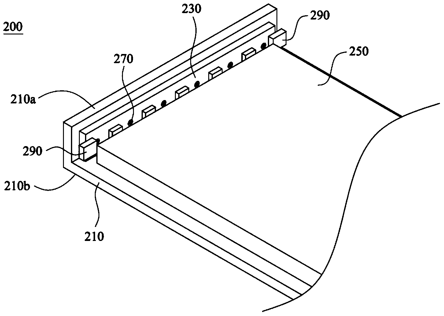
[0005] Therefore, when the light source module 200 is used in the backlight module, it is not conducive to the structural design of the narrow frame, and the connectors 290 located at both ends of the light bar will make it close to the There are dark bands at the position of the frame, which seriously affects the optical effect
When the light source module 200 is used in a lamp, it also restricts the structural design of the lamp and affects the lightness and aesthetic appeal of the lamp

Method used


Image

  • Light bar structure, light source module and lamp
  • Light bar structure, light source module and lamp
  • Light bar structure, light source module and lamp

Examples


Embodiment Construction

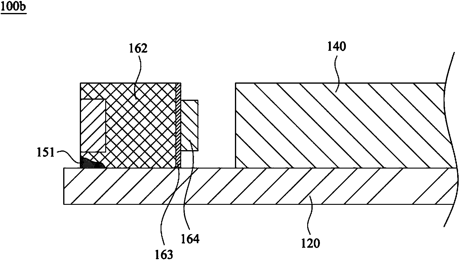
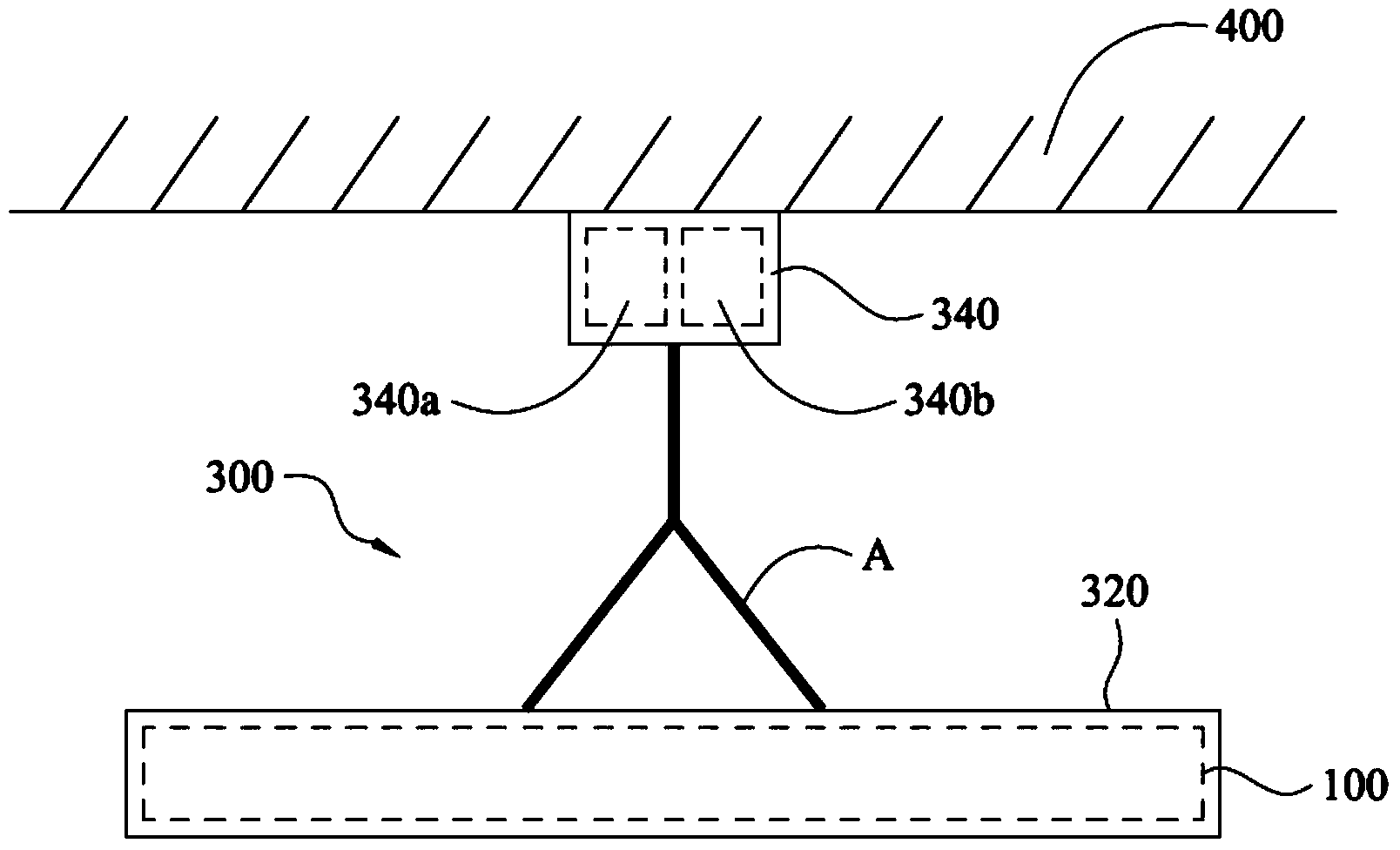
[0033] Please refer to figure 2 and image 3 , are respectively a structural schematic diagram of a light source module and a structural schematic diagram of a light bar provided by an embodiment of the present invention. The light source module 100 of this embodiment can be applied to a backlight module or a lamp. The light source module 100 includes a carrier 120 , a light guide plate 140 and a light bar structure 160 . Both the light guide plate 140 and the light bar structure 160 are disposed on the carrier 120 . Wherein, the light guide plate 140 has a light incident surface 140a. The light bar structure 160 is disposed on a side close to the light incident surface 140 a of the light guide plate 140 , so that the light provided by the light bar structure 160 can enter the light guide plate 140 from the light incident surface 140 a. It should be noted that when the light source module 100 is applied in a backlight module, the carrier 120 referred to here can be a back...


PUM


Abstract

The invention provides a light bar structure, a light source module and a lamp. The light bar structure comprises a substrate, an electrical unit and a plurality of light emitting diodes; the substrate comprises a first face, the electrical unit comprises a light source setting part, at least one flexible connecting piece and at least one electrical connecting terminal. The light source setting part is connected with the first face of the substrate, and one end of each flexible connecting piece is connected with the light source setting part. Each electrical connecting terminal is correspondingly connected to the other end of one flexible connecting piece, the electrical connecting terminals are arranged on positions which are far from the first face of the substrate, and the light emitting diodes are arranged on the light source setting part. In the light bar structure provided by the invention, by changing the positions of the electrical connecting terminals, the width or the thickness of the light bar structure can be flexibly adjusted, and therefore demands of narrow-edge backlight module can be better satisfied.

Description

[0001] This application claims the priority of a Taiwan patent application filed on January 28, 2014 with application number 103103237 and an invention title of "light bar structure, light source module and lamp", the entire content of which is incorporated in this application by reference. technical field [0002] The present invention relates to the technical field of lighting equipment, and more specifically relates to a light bar structure, a light source module and a lamp. Background technique [0003] The light source module has been widely used in backlight modules or lamps. Please refer to figure 1 , figure 1 It is a structural schematic diagram of a known light source module. The known light source module 200 includes a carrier 210 , a light bar 230 and a light guide plate 250 . Wherein, the carrier 210 has a folded edge 210a and a bottom surface 210b. The light bar 230 is fixed on the folded edge 210 a in a lateral locking manner through the fixing member 27...

Claims


Application Information

Patent Timeline
Patent Type & Authority Applications(China)
IPC IPC(8): F21S2/00F21V23/06F21V19/00F21V29/00F21Y101/02F21V29/50
CPCH05K1/028H05K2201/053H05K2201/055H05K2201/056G02B6/0083G02B6/0085F21S4/28F21Y2103/10F21Y2115/10H05K1/189F21V23/06F21V23/009F21V23/008F21V2200/20
Inventor 叶修宏钟智贤
Owner RADIANT GUANGZHOU OPTO ELECTRONICS
Learn More