

Multifunctional LED (light emitting diode) lamp cap connection mechanism
A technology of LED lamp holders and connecting mechanisms, which is applied in the direction of lighting devices, light sources, and parts of lighting devices, can solve the problems of shortened life, increased use cost, and easy burnout, and achieves reduced manufacturing costs, improved manufacturing efficiency, and better use Effect of life improvement
Inactive Publication Date: 2014-06-11
黄泰瑜
View PDF3 Cites 0 Cited by
- Summary
- Abstract
- Description
- Claims
- Application Information
AI Technical Summary
Problems solved by technology
[0002] LED lights generate a lot of heat when they work. If the heat dissipation is not smooth, it is easy to burn out its drive power (transformation) components, LED chips and other components, which will greatly reduce the service life of LED lights and increase the cost of use.
[0003] Existing LED lamps have significant energy savings, but their manufacturing and purchase costs are high, and their service life is far below the theoretical value
[0004] In the existing LED lamp, a heat dissipation mechanism is provided between the lamp cap connection mechanism and the LED chip board, and an assembly chamber for installing a driving power supply (transformation) assembly is arranged in the middle of the heat dissipation mechanism. There are several heat sinks arranged radially, and the entire heat sink has no transparent heat dissipation channels from one side to the other (the air crosses the convection channel), the air cannot be convected horizontally, the heat dissipation effect is poor, and the accumulated temperature of the component cavity is as high as 80 degrees Celsius or more. It is easy to burn out its drive power (transformation) components, LED chips and other components, which shortens the service life and greatly increases the cost of using LED energy-saving lamps, making LED lamps common. The actual service life is far less than the theoretical value, and the cost performance is far lower. Not only that, the heat dissipation mechanism with several radially arranged heat sinks around the sealed component cavity has complicated processing technology, many consumables, and high manufacturing cost.
Method used
View moreImage
Smart ImageViewing Examples

Examples
Embodiment Construction
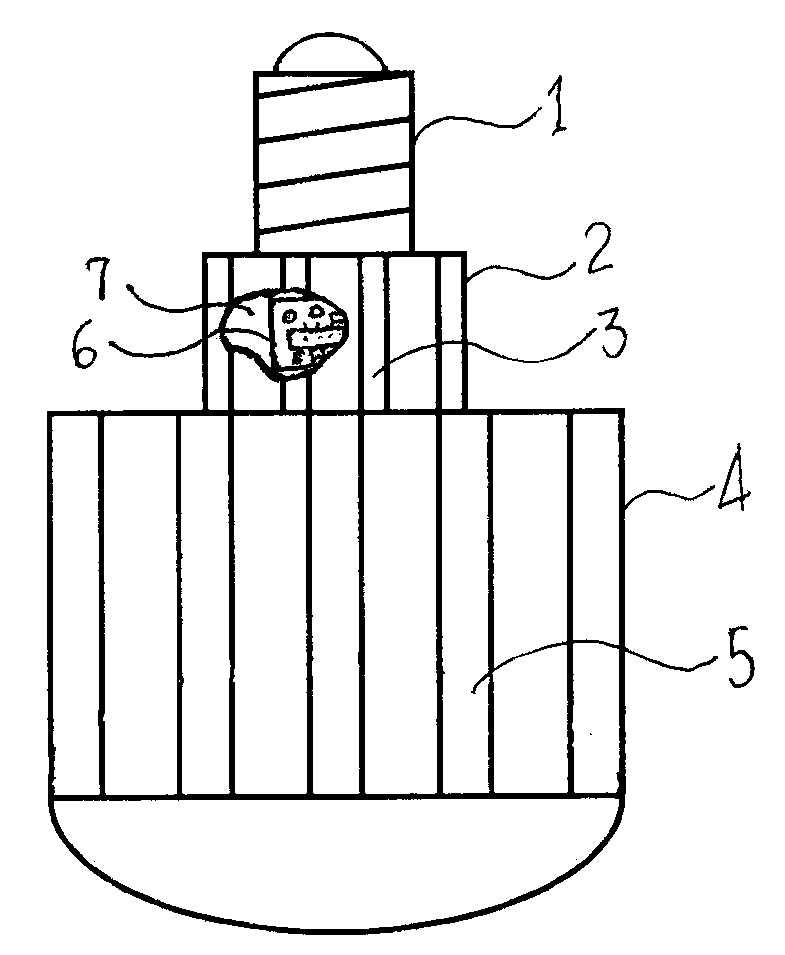
[0015] As shown in the figure, the multifunctional LED lamp cap connection mechanism of the present invention includes a lamp cap 1, a heat dissipation mechanism 4, and a lamp cap connection mechanism 2 connected with the lamp cap 1 and the heat dissipation mechanism 4 respectively. The connection mechanism 2 has a component cavity 7 communicating with the heat dissipation port 3, and the drive power component 6 of the LED lamp is installed in the component cavity 7. There is a transparent air transverse direction between the cooling fins of the heat dissipation mechanism 4, which can allow the air to traverse the convection. Convection channel 5.
Login to View More PUM
 Abstract
The invention discloses a multifunctional LED (light emitting diode) lamp cap connection mechanism and aims to overcome the shortcomings that the conventional LED lamp is poor in heat dissipation effect, short in service life, complicated in structure, high in consumption, high in manufacturing cost, low in cost-performance ratio and the like. Heat dissipation openings are formed in the wall of the lamp cap connection mechanism; the lamp cap connection mechanism is provided with a component cavity communicated with the heat dissipation openings; a driving power supply component for an LED lamp is arranged in the component cavity; through transverse air convection channels capable of enabling air to transversely penetrate in a convection manner are formed among all heat dissipation sheets of a heat dissipation mechanism. The multifunctional LED lamp cap connection mechanism is used for the LED lamp; compared with the conventional LED energy-saving lamp, the multifunctional LED lamp cap connection mechanism disclosed by the invention has a simplified structure, and is easy to manufacture, good in heat dissipation effect and low in use cost; under the same condition, a test detection result shows that the accumulated temperature of the LED lamp is reduced by over 20 percent; the service lives of structural members such as an LED chip and a driving power supply are prolonged by 5.6 times; consumables are saved by 30 percent; the manufacturing cost is reduced by 40 percent; the cost-performance ratio is doubled.
Description
technical field [0001] The invention relates to a component of an LED lamp, in particular to a multifunctional LED lamp head connection mechanism. Background technique [0002] LED lights generate a lot of heat when they work. If the heat dissipation is not smooth, it is easy to burn out its drive power (transformer) components, LED chips and other components, which will greatly reduce the service life of the LED lights and increase the cost of use. [0003] Existing LED lamps can save energy significantly, but their manufacturing and purchase costs are high, and their service life is far below the theoretical value. [0004] In the existing LED lamp, a heat dissipation mechanism is provided between the lamp cap connection mechanism and the LED chip board, and an assembly chamber for installing a driving power supply (transformation) assembly is arranged in the middle of the heat dissipation mechanism. There are several heat sinks arranged radially, and the entire heat sink...
Claims
Login to View More Application Information
Patent Timeline
 Patent Type & AuthorityApplications(China)
IPC IPC(8): F21V21/002F21Y101/02
Inventor黄子晋黄子恒黄泰瑜
Owner黄泰瑜