
Humidity sensor based on multimode fiber core and fiber grating and preparation method of humidity sensor

A humidity sensor and fiber grating technology, applied in the field of fiber grating sensors, can solve the problems of improving humidity sensitivity, increasing manufacturing cost and packaging difficulty, and complex manufacturing process of coated fiber grating humidity sensor.

Inactive Publication Date: 2014-06-11
XI'AN PETROLEUM UNIVERSITY
View PDF2 Cites 12 Cited by
  • Summary
  • Abstract
  • Description
  • Claims
  • Application Information

AI Technical Summary

Problems solved by technology

However, the manufacturing process of these coated fiber Bragg grating humidity sensors is complex, the degree of practicality is low, and the humidity sensitivity still needs to be improved.
Therefore, it is difficult to meet the needs of practical applications
Moreover, in order to solve the problem of cross-sensitivity between temperature and humidity, most fiber grating-based humidity sensors use two fiber gratings, which will increase the production cost and packaging difficulty to a certain extent, and limit the further practical application of fiber grating humidity sensors.

Method used


Image

  • Humidity sensor based on multimode fiber core and fiber grating and preparation method of humidity sensor
  • Humidity sensor based on multimode fiber core and fiber grating and preparation method of humidity sensor
  • Humidity sensor based on multimode fiber core and fiber grating and preparation method of humidity sensor

Examples


Embodiment Construction

[0019] The present invention will be described in further detail below in conjunction with the accompanying drawings and embodiments.

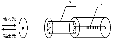
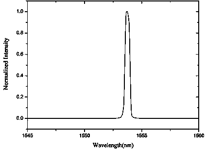
[0020] Such as figure 1 As shown, the fiber Bragg grating 1 we choose is the fiber Bragg grating 1 written on the Corning SM28 fiber. The period of the fiber Bragg grating 1 is 400um, and the central wavelength of the reflection peak is 1553.460nm. The transmission spectrum of the fiber Bragg grating 1 is as follows: figure 2 , where the ordinate is the normalized intensity, and the abscissa is the wavelength.

[0021] Strip the coating from a 35cm-long multimode optical fiber (S105 / 125), wipe it clean with alcohol, and put it in hydrofluoric acid with a concentration of 45% to remove the cladding of the optical fiber. Multimode fiber cores with different diameters can be obtained by controlling the etching time. After 10 minutes of corrosion, the multimode fiber core 2 is taken out and washed repeatedly with distilled water to remove residu...


PUM

PropertyMeasurementUnit
lengthaaaaaaaaaa
wavelengthaaaaaaaaaa

Abstract

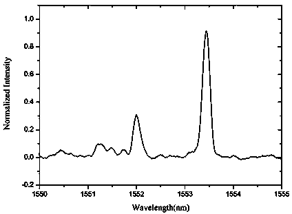
The invention relates to a humidity sensor based on a multimode fiber core and a fiber grating and a preparation method of the humidity sensor. The humidity sensor comprises the fiber grating, wherein the multimode fiber core is welded between the fiber grating and a single-mode fiber. The preparation method comprises the following steps: (1) stripping a coating layer from a multimode fiber, wiping the multimode fiber by utilizing alcohol, putting the multimode fiber into 45% hydrofluoric acid, and removing a coating layer from the multimode fiber; (2) after the multimode fiber is corroded, taking out the multimode fiber core, and repeatedly cleaning the multimode fiber core by utilizing distilled water to remove residual spent acid, so as to obtain the multimode fiber core; and (3) flatly cutting two ends of the multimode fiber core, and welding the multimode fiber core between the fiber grating and the single-mode fiber by virtue of a fiber fusion splicer, so as to form cascade connection between a single mode-multimode fiber core-single mode fiber structure and the fiber grating. According to the humidity sensor, when the external humidity is changed, a spectrum is changed, and the energy of a fundamental mode of the fiber core of the fiber grating is changed; when the external temperature is changed, the wavelength of the fundamental mode of the fiber core of the fiber grating is changed; the humidity sensor has the advantages that the fabrication is simple, the measuring accuracy is high, and the temperature and the humidity can be simultaneously measured.

Description

technical field [0001] The invention belongs to the technical field of optical fiber grating sensors, in particular to a humidity sensor based on a multimode fiber core and an optical fiber grating, which can simultaneously measure humidity and temperature. Background technique [0002] At present, the humidity sensor based on the principle of optical fiber sensing has the characteristics of no electromagnetic interference, corrosion resistance, good stability, high sensitivity, and easy networking and sensor integration. In the research and development of humidity sensors, it has attracted people. widespread attention. At present, fiber grating type, interference type and light intensity modulation type fiber optic humidity sensors have been developed. Fiber Bragg Grating (Fiber Bragg Grating) is the focus of research on fiber-optic humidity sensors because of its compact structure, wavelength modulation, and ease of networking and multiplexing. Since fiber Bragg grating ...

Claims


Application Information

Patent Timeline
Patent Type & Authority Applications(China)
IPC IPC(8): G01N21/25G01D5/28
Inventor 邵敏乔学光李利品贾振安傅海威李辉栋
Owner XI'AN PETROLEUM UNIVERSITY
Learn More