
Multi-ring micronizer grinding cavity, multi-ring micronizer and intelligent multi-ring micronizer system

A technology of micro-powder milling and grinding chamber, which is applied in grain processing and other directions, and can solve problems such as inability to apply, waste of stone resources, failure to meet fineness requirements, etc.

Active Publication Date: 2014-06-18
上海建冶路桥机器设备有限公司
View PDF13 Cites 10 Cited by
  • Summary
  • Abstract
  • Description
  • Claims
  • Application Information

AI Technical Summary

Problems solved by technology

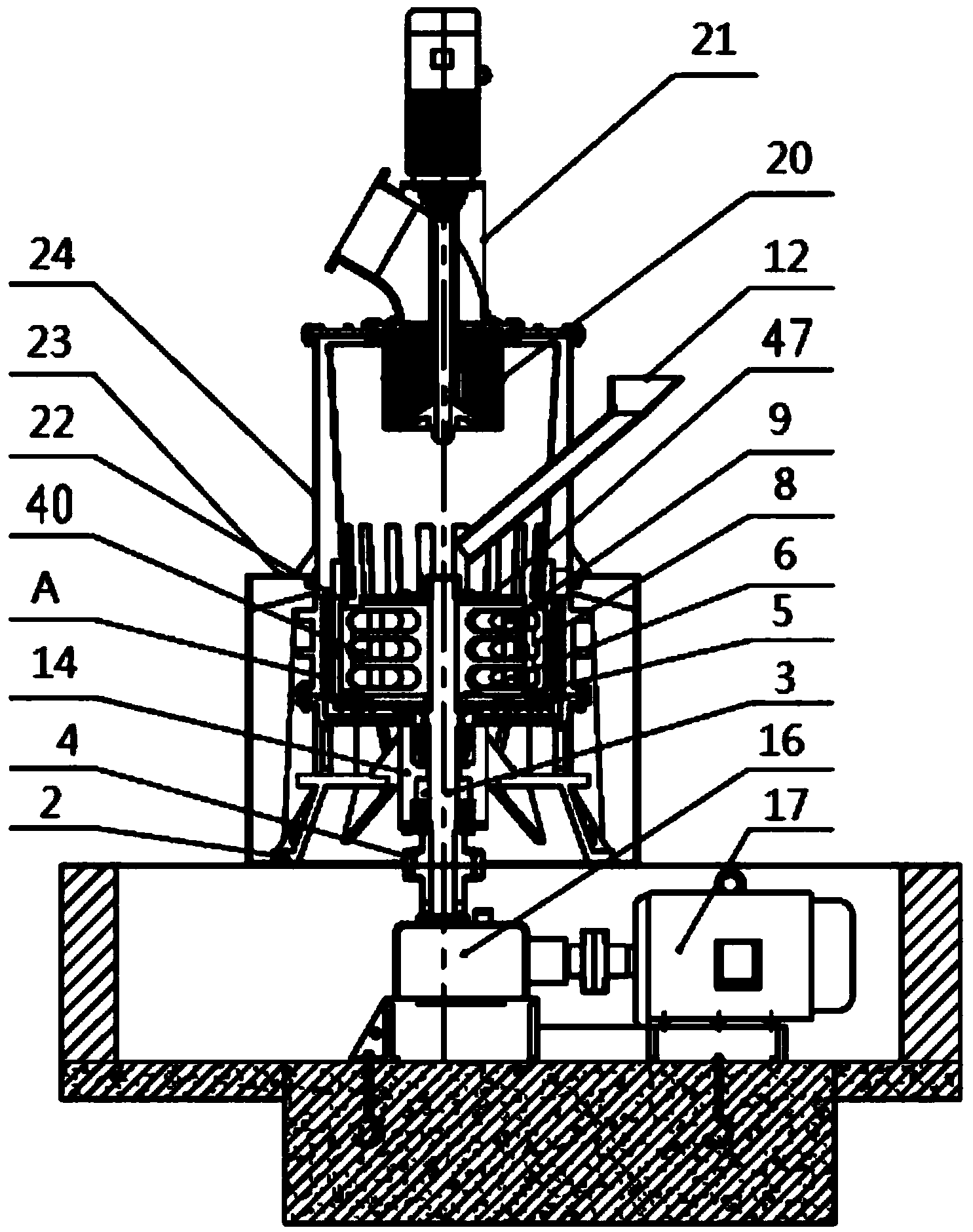
[0003] One of the objectives of the present invention is to provide a multi-ring micro-powder mill and an intelligent multi-ring micro-powder mill system, which mainly solves the problem that gravel and stone powder in the existing stone mining process cannot be used if they cannot meet the fineness requirements, resulting in the loss of stone resources. The technical problem of waste, it can turn stone or various mineral wastes into treasures through this production and processing system, and take into account the energy-saving and environmental protection requirements of the environment during the production process

Method used


Image

  • Multi-ring micronizer grinding cavity, multi-ring micronizer and intelligent multi-ring micronizer system
  • Multi-ring micronizer grinding cavity, multi-ring micronizer and intelligent multi-ring micronizer system
  • Multi-ring micronizer grinding cavity, multi-ring micronizer and intelligent multi-ring micronizer system

Examples


Embodiment Construction

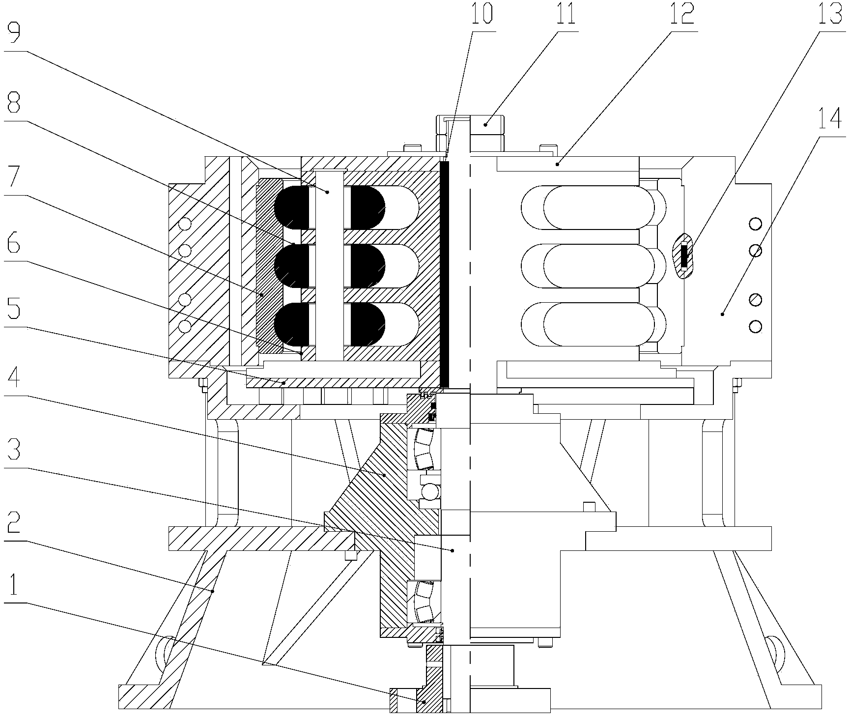
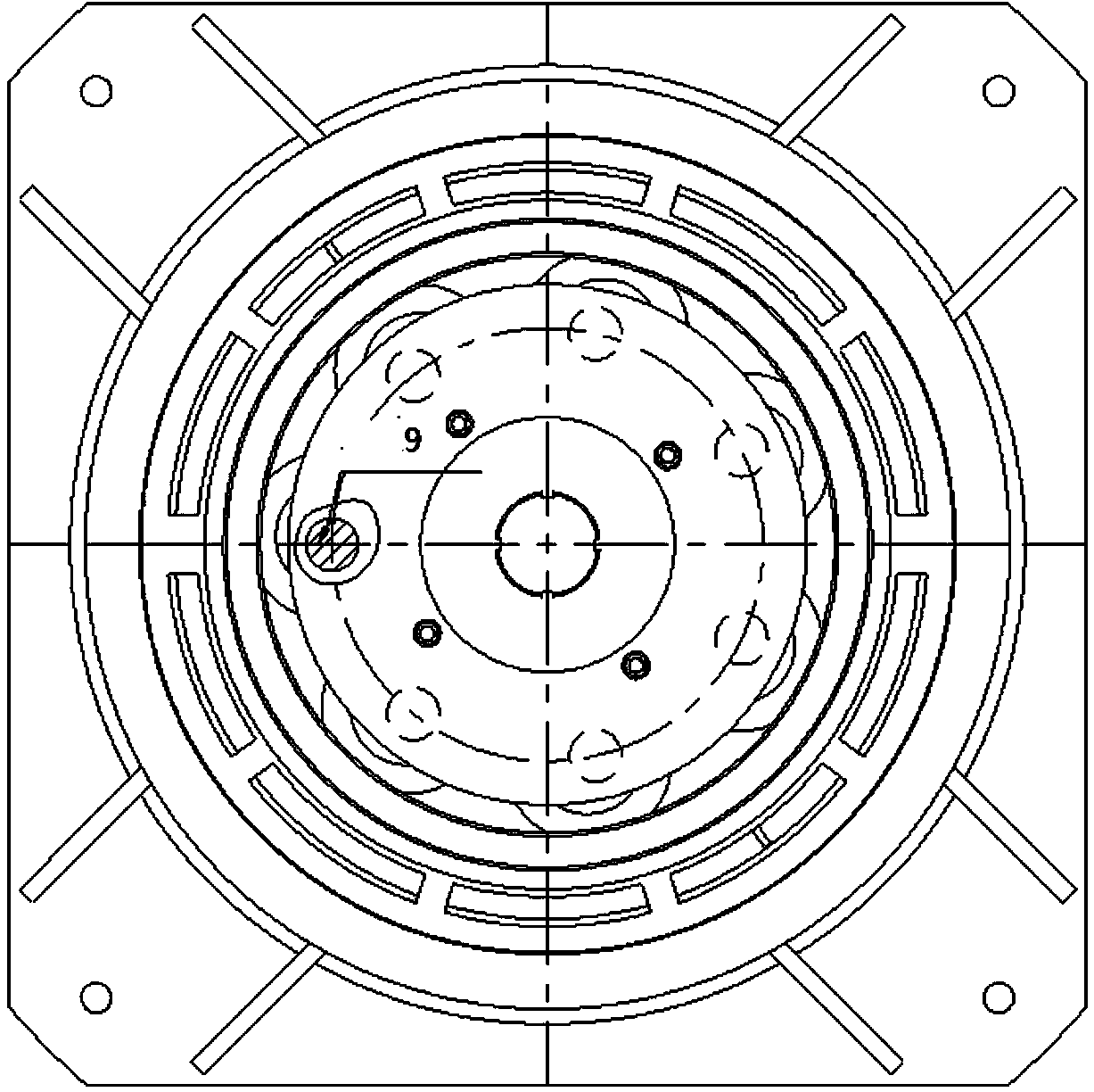
[0021] see figure 2 , 3 , which is the structural schematic diagram of the grinding chamber of the multi-ring micropowder mill of the present invention. figure 2 It includes machine base 2, coupling 1, transmission bearing cylinder 4, transmission main shaft 3, lower bulk material disc 5, multi-layer grinding disc 6, roller pin 9, combined drum-shaped grinding roller 8, inner wall with multi-layer semicircle The grinding ring 7, the grinding ring limit key 13, the upper bulk plate 12, the combined locking nut 11, the long limit key 10, the split middle casing 14, etc. Wherein: the outer shape of the drum-shaped grinding roller 8 is matched with the semicircular slideway of the grinding ring 7 with the multi-layer semicircular slideway on the inner wall.

[0022] The specific structure of the multi-ring micro-powder grinding chamber is as follows: the transmission bearing cylinder 4 is fixed in the machine base 2 by locking bolts, the coupling 1 is installed on the lower sh...


PUM


Abstract

The invention relates to a multi-ring micronizer grinding cavity, a multi-ring micronizer and an intelligent multi-ring micronizer system. The multi-ring micronizer grinding cavity comprises a rotating grinding device connected with a transmission main shaft, wherein the rotating grinding device is composed of multiple layers of grinding discs, coupling drum-shaped grinding rollers and a roller shaft pin; the roller shaft pin is arranged in multiple layers of grinding discs, the coupling drum-shaped grinding rollers take a single grinding roller inner through hole as a standard and can be positioned by depending on the roller shaft pin, and the coupling drum-shaped grinding rollers are arranged at interval regions of the multiple layers of grinding discs according to groups; a shell of the outer side of the rotating grinding device is provided with a grinding ring, wherein the inner wall of the grinding ring is provided with multiple layers of half round sliding channels, and horizontal centers of the half round sliding channels of the grinding ring and a horizontal center of a grinding roller of a corresponding layer arranged on a rotating grinding roller assembly are horizontally arranged on a line. The multi-ring micronizer with the multi-ring micronizer grinding cavity and the system mainly solve the technical problem that the broken stones and mountain flour in a stone exploitation process can not achieve a fineness requirement, the application is not performed, a stone resource is wasted, the stone waste is recycled through a manufacture processing system, and an environment energy-saving environment-friendly requirement is achieved in a productive process.

Description

technical field [0001] The invention relates to a material grinding structure and system, in particular to a multi-ring micro-powder grinding chamber, a multi-ring micro-powder mill and an intelligent multi-ring micro-powder grinding system. Background technique [0002] In recent years, with the requirements of new energy conservation and environmental protection, and with the development of science and technology, the application of ore micropowder has become more and more extensive. As a functional filler, micropowder has higher and higher requirements for the fineness of use, and the wastes (such as: crushed stone and stone powder) in the process of stone mining will also increase. It cannot be applied unless the fineness is required, resulting in a waste of stone resources. Therefore, how to turn waste into treasure has become the goal of corporate environmental and social benefits. SUMMARY OF THE INVENTION [0003] One of the objects of the present invention is to ...

Claims


Application Information

Patent Timeline
IPC IPC(8): B02C15/12B02C15/08B02C21/00
Inventor 杨晓斌杨晓艳杨金国林维佳
Owner 上海建冶路桥机器设备有限公司
Learn More