Power truck for 100% low-floor vehicle

A power bogie and low-floor technology, which is applied to bogies, transmission devices driven by electric motors, railway car body parts, etc., can solve the problems of difficult control system design, poor stress conditions, and poor guidance of independent wheelsets and other issues, to achieve the effect of light weight, simple structure and low production cost

Active Publication Date: 2014-06-18
CHENGDU XINZHU ROAD & BRIDGE MASCH CO LTD
View PDF6 Cites 7 Cited by
  • Summary
  • Abstract
  • Description
  • Claims
  • Application Information

AI Technical Summary

Problems solved by technology

The bogie of the traditional wheel set mostly adopts the motor reducer and is placed outside the frame together. However, due to the limitation of the width of the car body, it is necessary to reduce the lateral width of the secondary support to adapt, so the stress condition is not very good.
[0004] However, the independent wheelset has poor guidance and is easy to derail, and the design of the control system is very difficult and costly

Method used


Image

  • Power truck for 100% low-floor vehicle
  • Power truck for 100% low-floor vehicle
  • Power truck for 100% low-floor vehicle

Examples


Embodiment Construction

[0020] Below in conjunction with accompanying drawing, the present invention is described in detail.

[0021] Best practice:

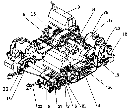
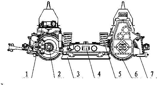
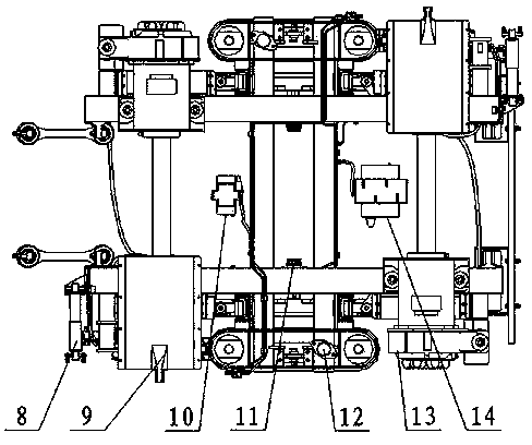
[0022] Such as figure 1 , 2 , 3, a power bogie for 100% low-floor vehicles includes a frame 20 and two axles 17, the frame 20 includes two side beams with a concave middle and parallel to each other and connected to the two side beams Cross beams parallel to each other between the concave parts in the middle of the beam. The side beam is a bow-shaped structure welded by weathering steel so as to reduce the height of the bottom plate; the cross beam adopts seamless steel pipe so as to reduce the overall weight of the present invention.

[0023] The two ends of the axle 17 are sequentially connected to the axle box 16, the elastic wheel 6 and the brake disc 21 from the inside to the outside, and are installed on the bottom of the side beam through the primary suspension mounts 26 and the primary suspension 23 at the front and rear ends of the axle box...


PUM


Abstract

The invention discloses a power truck for a 100% low-floor vehicle. The power truck comprises a framework and two axels. The framework comprises two side beams and two cross beams. The two ends of each axel are respectively connected with an axle box, an elastic wheel and a brake disc and are installed at the bottom of the corresponding side beam. A sand box is arranged on the top of one end of each side beam. An air compressor is installed on each sand box. The middle portion of each side beam is recessed, and a transverse stop is arranged on the inner side of each side beam. A secondary suspension mounting base of the two cross beams is arranged outside the side beams. A secondary suspender, a vertical stop and a vertical damper are arranged on the secondary suspension mounting base. A magnetic track braking device is connected between the every two axle boxes on the same side. The ends, which are the same, of the two side beams are respectively provided with a traction rod. The ends, which are different, of the two side beams are provided with a transverse damper and a braking clamp respectively. The braking clamp is connected with a braking release unit and a braking hydraulic unit. All the components except the traction rod are symmetrical about the center of the framework. By means of the power truck, a low floor surface of the vehicle is overall through, and the specification requirements of the 100% low-floor vehicle are met; the power truck can rotate by 180 degrees as a whole to be used, thereby being high in flexibility.

Description

technical field [0001] The invention relates to the technical field of rail vehicles, in particular to a power bogie for 100% low-floor vehicles. Background technique [0002] Low-floor vehicles are one of the important tools of urban rail transit. They are popular in cities for their convenience for passengers, diverse marshalling, flexible operation, and sharing of existing bus stops and road resources. The low-floor vehicle bogie, as the out-of-shape part of the low-floor vehicle, is the key component to realize low-floor vehicles. [0003] At present, there are two types of power bogies for low-floor vehicles in China: traditional wheelsets and independent wheelsets. The bogie of the traditional wheel set mostly adopts the motor reducer and is placed outside the frame together. However, due to the limitation of the width of the car body, it is necessary to reduce the lateral width of the secondary support to adapt, so the stress condition is not very good. . [0004] ...

Claims


Application Information

Patent Timeline
Patent Type & Authority Applications(China)
IPC IPC(8): B61F5/52B61C9/38
Inventor 黄永强董红波骆顺东刘强舒斌
Owner CHENGDU XINZHU ROAD & BRIDGE MASCH CO LTD
Why Eureka
Try Eureka