Construction method of concrete framework structure with beam end constraining and releasing functions

A construction method and frame structure technology, applied in the direction of building structures, buildings, building components, etc., can solve the problems of large bearing capacity, large effective area of ​​bending resistance, large rigidity, etc., and achieve the effect of releasing constraints and improving the effect of earthquake resistance

Active Publication Date: 2014-06-18
ZHEJIANG UNIV OF TECH +2
View PDF5 Cites 2 Cited by
  • Summary
  • Abstract
  • Description
  • Claims
  • Application Information

AI Technical Summary

Problems solved by technology

[0004] In order to overcome the deficiencies of the beam end and the slab connection structure existing in the existing concrete frame structure, the beam end has a larger bending effective area, greater rigidity, larger bearing capacity than the column body, and poor seismic effect, the present invention provides a lifting beam Construction method of concrete frame structure with beam end restraint release function for restraint between floor and slab and improved seismic effect

Method used


Image

  • Construction method of concrete framework structure with beam end constraining and releasing functions
  • Construction method of concrete framework structure with beam end constraining and releasing functions

Examples


Embodiment Construction

[0032] The present invention will be further described below in conjunction with the accompanying drawings.

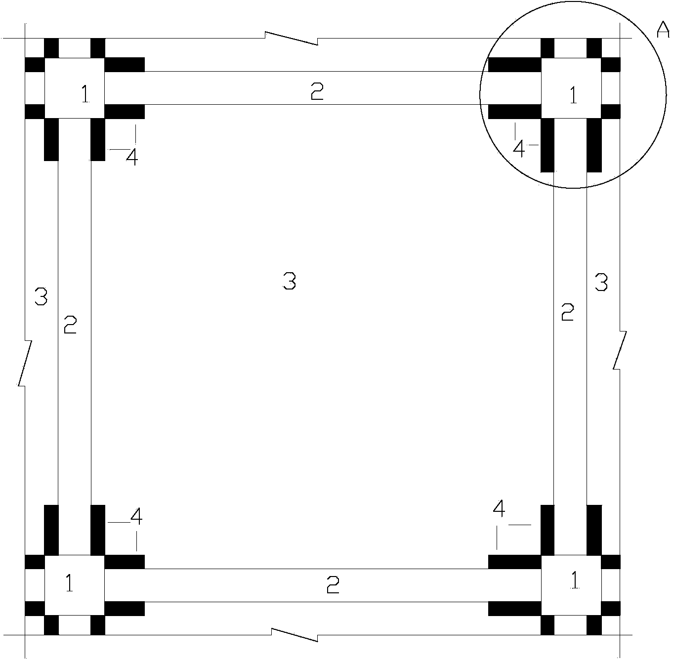
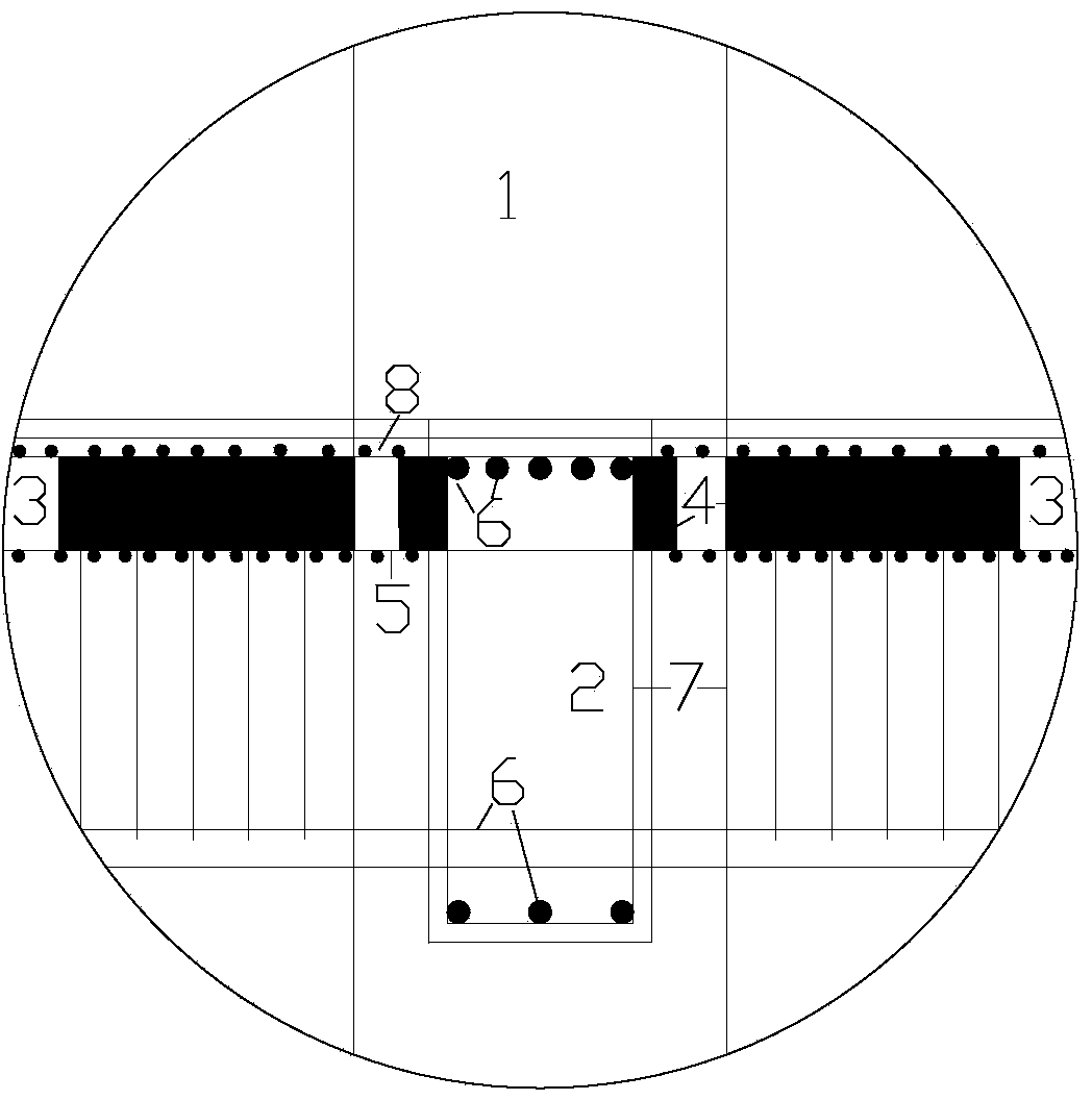
[0033] refer to figure 1 and figure 2 , a method for constructing a concrete frame structure with a beam end restraint release function, comprising the following steps:

[0034] 1) Position the floor column, arrange the column reinforcement, and form the formwork to the bottom of the beam

[0035] First, establish the position of column 1 and the position of the formwork. For the lengthening of shorter column longitudinal reinforcement, lap joint or welding can be used. If conditions permit, welding should be adopted as much as possible. Encryption, column formwork and formwork support and column reinforcement layout are carried out alternately from the vertical formwork to the bottom of the beam, and the column reinforcement layout passes through the upper floor. Pay attention to the densification of the stirrups at the upper end of the column and at the joints of...


PUM


Abstract

The invention discloses a construction method of a concrete frame structure with beam end restraining and releasing functions. The construction method comprises the following steps of (1) establishing the positioning of floor columns, distributing column ribs and establishing templates to beam bottoms; (2) establishing a floor system template supporting frame, and establishing a floor system template; (3) distributing plate bottom steel bars; (4) putting beam main ribs into template grooves; (5) distributing constraint removing plates on the side surfaces of beam ends, wherein the positions of floor plate bottom ribs which are anchored on beams or cross the beams can be adjusted, the constraint removing plates are distributed on the side surfaces of the beam ends, the bottom surfaces of fine aggregate concrete layers of the constraint removing plates are attached to stirrups at the beam sides, the thickness direction of the constraint removing plates is vertical to the axial direction of the beam, and the constraint removing plates are vertically arranged on the upper surfaces of the plate bottom steel bars; (6) distributing plate surface steel bars, wherein the constraint removing plates are clamped between the plate bottom steel bars and the plate surface steel bars; (7) integrally pouring concrete on a floor system, wherein the constraint removing plates are sealed on the beam side surfaces. According to the construction method of the concrete framework structure with the beam end constraining and releasing functions, which is disclosed by the invention, the constraint between the beams and floor plates is removed, and the anti-seismic effect is increased.

Description

technical field [0001] The invention relates to a concrete frame structure, in particular to a method for constructing a concrete frame structure. Background technique [0002] The main seismic design principles of concrete frame structures are "strong column weak beam", "strong shear weak bending" and "strong node weak member". According to this design principle, when the concrete frame structure encounters an earthquake, the frame structure first Damage occurs, and the safety of columns and joints is ensured, so as to ensure that the overall structure will not collapse. The Wenchuan Earthquake disaster in my country shows that the cast-in-place slab widely used at present can effectively prevent the slab from detaching and hurting people. are rarely seen, which shows that the design principles of the structure have not been effectively realized. One of the reasons for the analysis is that the existing design codes in my country are extracted from the summary of earthquake...

Claims


Application Information

Patent Timeline
Patent Type & Authority Applications(China)
IPC IPC(8): E04B1/19E04B5/32E04B1/98
Inventor 杨俊杰章雪峰戴晓芳闻卫东郑丽海
Owner ZHEJIANG UNIV OF TECH
Why Eureka
Try Eureka