Fuel accelerator of internal combustion engine

A technology of accelerators and internal combustion engines, applied in the direction of internal combustion piston engines, combustion engines, machines/engines, etc., can solve the problems of incomplete function, low utilization rate of magnetic pole surface, small effective range, etc., and achieve high utilization rate of magnetic pole surface. , The effect of fuel saving and emission reduction is good, and the effective range is large.

Inactive Publication Date: 2014-06-18
刘华
View PDF6 Cites 2 Cited by
  • Summary
  • Abstract
  • Description
  • Claims
  • Application Information

AI Technical Summary

Problems solved by technology

[0004] This magnetization device is composed of two magnetizers, each magnetizer has only one permanent magnet, and the shielding layer and the through hole face the oil pipe and correspond to the oil pipe. The disadvantage of this structure is: because the magnetic force l

Method used


Image

  • Fuel accelerator of internal combustion engine

Examples


Embodiment

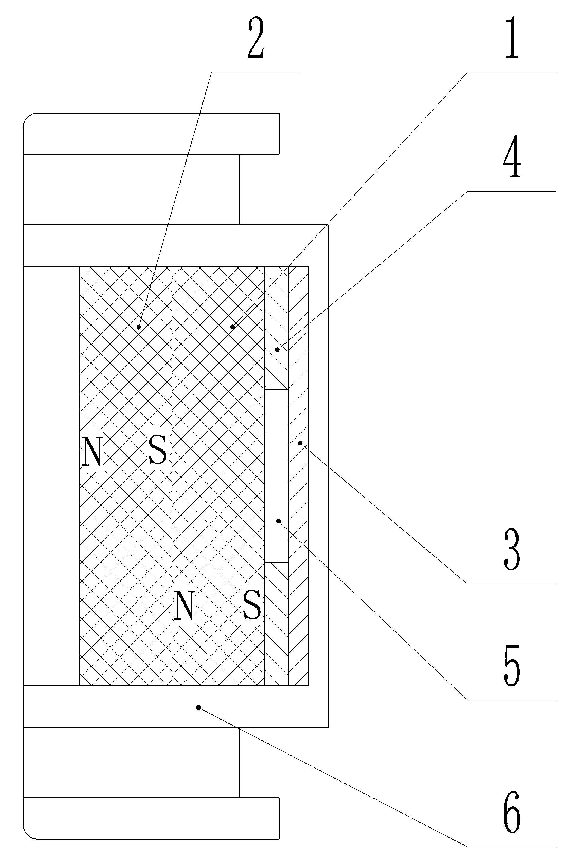
[0018] refer to figure 1 , a fuel booster for an internal combustion engine, including a magnetization device, the magnetization device includes two permanent magnets arranged in the casing 6, the different poles of the two permanent magnets are correspondingly stacked, and one of the permanent magnets The pole surface of the magnet corresponds to the oil pipe, and a shielding layer 3 is provided to overlap the pole surface of another permanent magnet.

[0019] Specifically, the two permanent magnets are a first permanent magnet 1 and a second permanent magnet 2, the N pole of the first permanent magnet 1 is stacked corresponding to the S pole of the second permanent magnet 2, and the N pole of the second permanent magnet 2 Facing the oil pipe during use, the S pole of the first permanent magnet 1 overlaps with the shielding layer 3 .

[0020] Shielding layer 3 is magnetic metal, such as iron, steel and so on.

[0021] An isolation layer 4 is provided between the shielding l...


PUM


Abstract

The invention discloses a fuel accelerator of an internal combustion engine. The fuel accelerator comprises a magnetizer and is characterized in that the magnetizer comprises two permanent magnets arranged in a shell, wherein different magnetic poles of the two permanent magnets are correspondingly superposed, the end surfaces of magnetic poles of one permanent magnet correspond to oil tubes, are provided with shielding layers and are superposed with the end surfaces of magnetic poles of the other permanent magnet; isolation layers are arranged between the shielding layers and the end surfaces of the magnetic poles; the middle parts of the isolation layers are provided with through holes. The fuel accelerator is provided with two magnets, and is high in magnetic field intensity; magnetic lines facing to the oil tubes are not shielded, effective magnetic lines can be fully utilized, the surface utilization ratio of the magnetic poles is high, the effective range is large, the action time is long, and the oil-saving and emission-reducing effects are better.

Description

technical field [0001] The invention relates to the field of internal combustion engines, in particular to a fuel accelerator for internal combustion engines. Background technique [0002] A permanent magnet is set on the fuel pipeline of the internal combustion engine. When the fuel fluid molecules pass through the magnetic field, the fluid molecules change their polarity and rearrange in an orderly manner; at the same time, the molecular clusters are crushed by the magnetic field, and the molecular bonds will be elongated, increasing the surface area of ​​the molecules and making the combustion process easier. More fully, so there is a certain fuel-saving effect, but also reduces exhaust emissions. [0003] The magnetizing device designed according to this principle, such as the structure disclosed in the patent of CN102619652A "A device for energy saving and emission reduction of internal combustion engine": a device for energy saving and emission reduction of internal co...

Claims


Application Information

Patent Timeline
IPC IPC(8): F02M27/04
CPCY02T10/12
Inventor 孟启平
Owner 刘华
Why Eureka
Try Eureka