Regulating valve

A control valve and valve seat technology, applied in the field of control valves, can solve the problems of valve service life, easy to produce cavitation, cavitation, complex process medium state, etc. Effect

Inactive Publication Date: 2014-06-18
CHONGQING CHUANWU INSTR
View PDF9 Cites 9 Cited by
  • Summary
  • Abstract
  • Description
  • Claims
  • Application Information

AI Technical Summary

Problems solved by technology

[0003] 1, figure 1 It is a schematic diagram of fluid flow in the straight-through valve in the prior art, figure 2 Generate cavitation and cavitation state diagrams for straight-through valves in the prior art, such as figure 1 and figure 2 As shown, the straight-through valve includes the straight-through valve seat A1, the straight-through valve core A2, and its flow path is "S"-shaped. When the process medium flows through the valve, the state is complicated, the flow resistance is large, and the pressure drop is obvious at the orifice. , the flow rate is high, it is easy to produce cavitation, cavitation and other phenomena, and the erosion of the sealing surface is also very serious, and the service life of the valve is affected;
[0004] 2. When the fluid passes through the regulating valve, the straight-through valve spool A2 is affected by the fluid pressure, which will produce a force opposite to the direction of movement, that is, the unbalanced force. In the straight-through valve, the direction of the unbalanced force is in the direction of the output force of the actuator. on the same line (see attached figure 2 ), the position of the straight-through valve spool A2 in the switching process is easily affected by the change of the unbalanced force, thus affecting the adjustment accuracy;
[0005] 3. In the case of the same flow capacity, the straight-through valve is bulky and heavy, and the larger the caliber, the more obvious it is;

Method used


Image

  • Regulating valve
  • Regulating valve
  • Regulating valve

Examples


Embodiment Construction

[0054] In order to make the purpose, technical solutions and advantages of the present invention clearer, the technical solutions in the present invention will be clearly and completely described below in conjunction with the accompanying drawings in the present invention. Obviously, the described embodiments are part of the embodiments of the present invention , but not all examples. Based on the embodiments of the present invention, all other embodiments obtained by persons of ordinary skill in the art without creative efforts fall within the protection scope of the present invention.

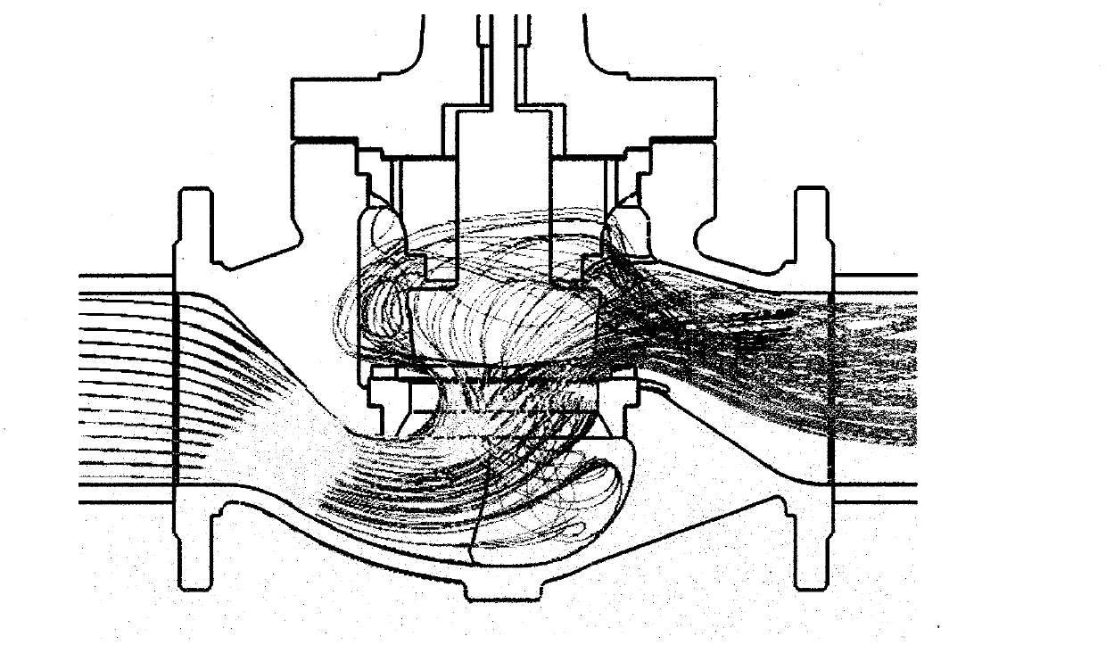
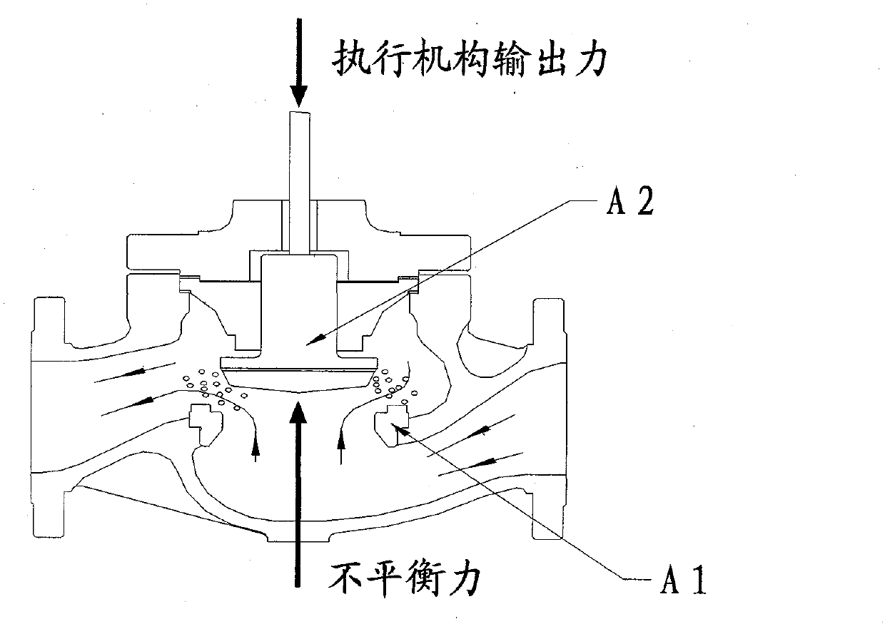
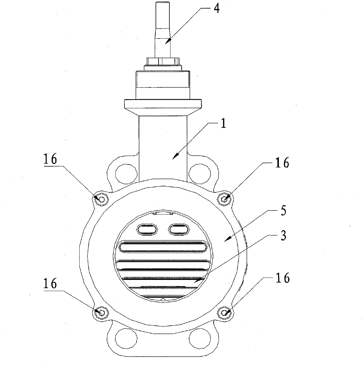
[0055] image 3 It is the front view of the regulating valve of the present invention, Figure 4 for image 3 sectional view, such as image 3 and Figure 4 As shown, the regulating valve of the present invention includes a valve body 1, a valve seat 2 is fixed inside the valve body 1, and a valve seat throttle 21 is provided on the valve seat 2 for fluid to flow through. Figure 5 It is a...


PUM


Abstract

The invention provides a regulating valve. The regulating valve comprises a valve body, wherein a valve seat is fixedly arranged inside the valve body, valve seat throttling openings which are used for fluid to flow through are formed in the valve seat, a pressing cover is fixedly arranged at one side of the valve body, a gap is formed inside the valve body by the pressing cover and the valve seat, a sliding plate which can slide up and down along the valve seat is inserted into the gap, a planar sealing pair is formed by the sliding plate and the valve seat, sliding plate throttling openings corresponding to the valve seat throttling openings are formed in the sliding plate, the valve seat throttling openings and the sliding plate throttling openings are staggered when the sliding plate moves up and down relative to the valve seat, so as to control the pressure and flow of the fluid flowing through the regulating valve, and a retaining ring which is used for compacting the sliding plate and the valve seat is further arranged between the sliding plate and the pressing cover. According to the regulating valve, when the fluid flows through the valve, the phenomena of gas etching and cavitation difficultly occur, the flushing damage to sealing faces is little, and the condition that the regulating accuracy of the regulating valve is poor due to the effect of unbalanced force during the opening / closing of a valve core is reduced.

Description

technical field [0001] The invention relates to fluid conveying systems in petroleum, metallurgy, chemical industry, power station, nuclear industry, etc., in particular to a regulating valve. Background technique [0002] Regulating valve is a device that controls the medium pressure of fluid on the conveying pipeline and regulates the flow rate. It is the execution unit in the industrial automation control system and an indispensable component in the adjustment system. It is an important link that forms the industrial automation system. According to its function, it can be divided into two types: cut-off and adjustment. At present, the more precise regulating valves used for flow control are mainly straight-through valves, and straight-through valves have the following disadvantages due to their structural characteristics: [0003] 1, figure 1 It is a schematic diagram of fluid flow in the straight-through valve in the prior art, figure 2 Generate cavitation and cavita...

Claims


Application Information

Patent Timeline
Patent Type & Authority Applications(China)
IPC IPC(8): F16K3/02F16K3/30F16K3/314F16K3/32F16K41/02
CPCF16K3/0209F16K3/18F16K3/30F16K3/314F16K3/32F16K41/02
Inventor 刘祥明盛洪蔡杰浩
Owner CHONGQING CHUANWU INSTR
Why Eureka
Try Eureka