Automatic calibration batching scale

An automatic calibration and batching scale technology, which is applied in the field of batching scales, can solve the problems that affect the quality stability of feed products, require very high physical strength, and the workload of calibration scales is large, so as to save labor costs, reduce calibration time, The effect of reducing labor intensity

Active Publication Date: 2014-06-18
扬州华美知识产权事务有限公司
View PDF5 Cites 6 Cited by
  • Summary
  • Abstract
  • Description
  • Claims
  • Application Information

AI Technical Summary

Problems solved by technology

[0003] General feed production enterprises need to calibrate the batching scales before production to ensure the accuracy and reliability of the batching scales; however, when the batching scales used in the market are calibrated now, people need to carry the weights to the batching scales one by one Carry out calibration; now an ordinary batching scale can batch batches of 5 tons, or even larger; so the workload of calibrating the scale is very large, and often the workload of calibrating the scale of a batching scale requires 5-6 people to spend nearly 30 It takes only a few minutes to move the weights up and down, and a feed factory often has multiple batching scales, which requires very high physical strength for the workers, and the time spent also affects normal production.
It is precisely because of the heavy workload and long time for scale calibration that many feed manufacturers often reduce the work by reducing the number of scale calibrations, but this also affects the quality stability of feed products

Method used


Image

  • Automatic calibration batching scale
  • Automatic calibration batching scale
  • Automatic calibration batching scale

Examples


Embodiment Construction

[0024] Below in conjunction with accompanying drawing and specific embodiment, further illustrate the present invention, it should be understood that these embodiments are only used to illustrate the present invention and are not intended to limit the scope of the present invention, after reading the present invention, those skilled in the art will understand various aspects of the present invention Modifications in equivalent forms all fall within the scope defined by the appended claims of this application.

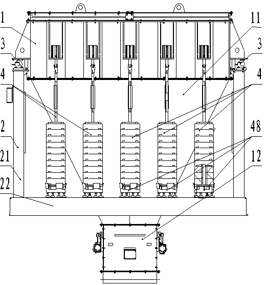
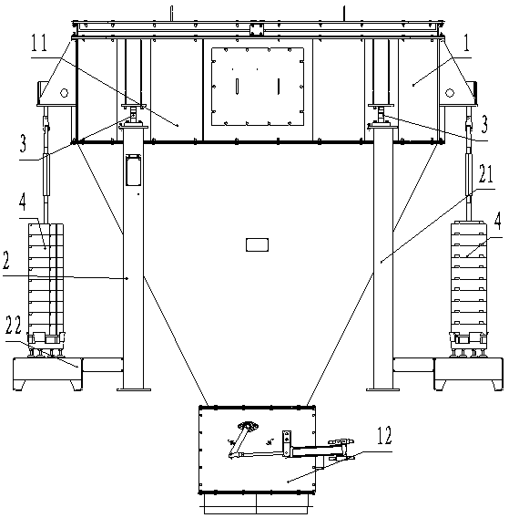
[0025] Such as figure 1 and figure 2 As shown, an automatic calibration batching scale is disclosed, which includes a scale body 1 , a bracket 2 , a load cell 3 and a scale calibration mechanism 4 . The scale body includes a scale bucket 11 and a gate 12 installed at the bottom of the scale bucket. The bracket includes outriggers 21 for supporting the scale body and supports 22 for placing weights. The scale body is installed on the supporting legs, and a load cell ...


PUM


Abstract

The invention discloses an automatic calibration batching scale. The automatic calibration batching scale comprises a scale body. The scale body is provided with a bracket. A weighing sensor is installed between the scale body and the bracket. A plurality of scale calibration mechanisms are installed on the scale body. The scale calibration mechanisms comprise hoisting devices installed on the scale body. The hoisting devices are provided with pull rods. The ends of the pull rods are provided with trays. The positions, on the upper portions of the trays, of the pull rods are sleeved with weights in a gapped mode. Weight bases are installed on the lower portions of the corresponding trays and used for receiving the weights. The weight bases are provided with gaps for avoiding the trays and the pull rods, so that interference in the trays and the pull rods is prevented. In the scale calibration process, the hoisting devices hoist the weights which need to be loaded on the scale body as needed, the weights which do not need to be loaded fall onto the weight bases, and the trays and the pull rods penetrate through the gaps of the weight bases. Manual handling of the weights is not required, the weight is loaded on the scale body by hoisting the weights through the hoisting devices, so that automatic scale calibration is achieved, and labor cost is reduced.

Description

technical field [0001] The invention relates to a batching scale, in particular to an automatic calibration batching scale used in feed batching. Background technique [0002] As the key equipment for quality measurement of feed processing enterprises, batching scales, the accuracy of their batching will be directly related to the stability of product quality of feed processing enterprises, the economy of breeding enterprises and our food safety. [0003] General feed production enterprises need to calibrate the batching scales before production to ensure the accuracy and reliability of the batching scales; however, when the batching scales used in the market are calibrated now, people need to carry the weights to the batching scales one by one Carry out calibration; now an ordinary batching scale can batch batches of 5 tons, or even larger; so the workload of calibrating the scale is very large, and often the workload of calibrating the scale of a batching scale requires 5-...

Claims


Application Information

Patent Timeline
IPC IPC(8): G01G23/01
Inventor 姜明明刘广道邹厚勇李庆凯郭学元徐登科
Owner 扬州华美知识产权事务有限公司
Why Eureka
Try Eureka