Argon excitation system of spectrograph

An excitation system and spectrometer technology, applied in the field of gas circuit system, can solve the problems of no strong blowing, single gas circuit, and no pressure transformer device in the argon gas circuit.

Active Publication Date: 2014-06-18
YANTAI DONGFANG ANALYTICAL INSTR +1
View PDF5 Cites 3 Cited by
  • Summary
  • Abstract
  • Description
  • Claims
  • Application Information

AI Technical Summary

Problems solved by technology

However, there is no improved design for the argon gas circuit. The argon gas circuit does not have a pressure changing dev

Method used


Image

  • Argon excitation system of spectrograph
  • Argon excitation system of spectrograph
  • Argon excitation system of spectrograph

Examples


Embodiment Construction

[0017] The specific embodiment of the present invention is described in detail below in conjunction with accompanying drawing:

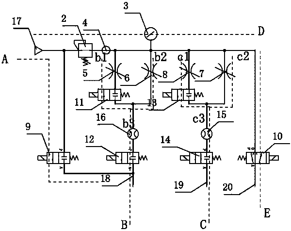
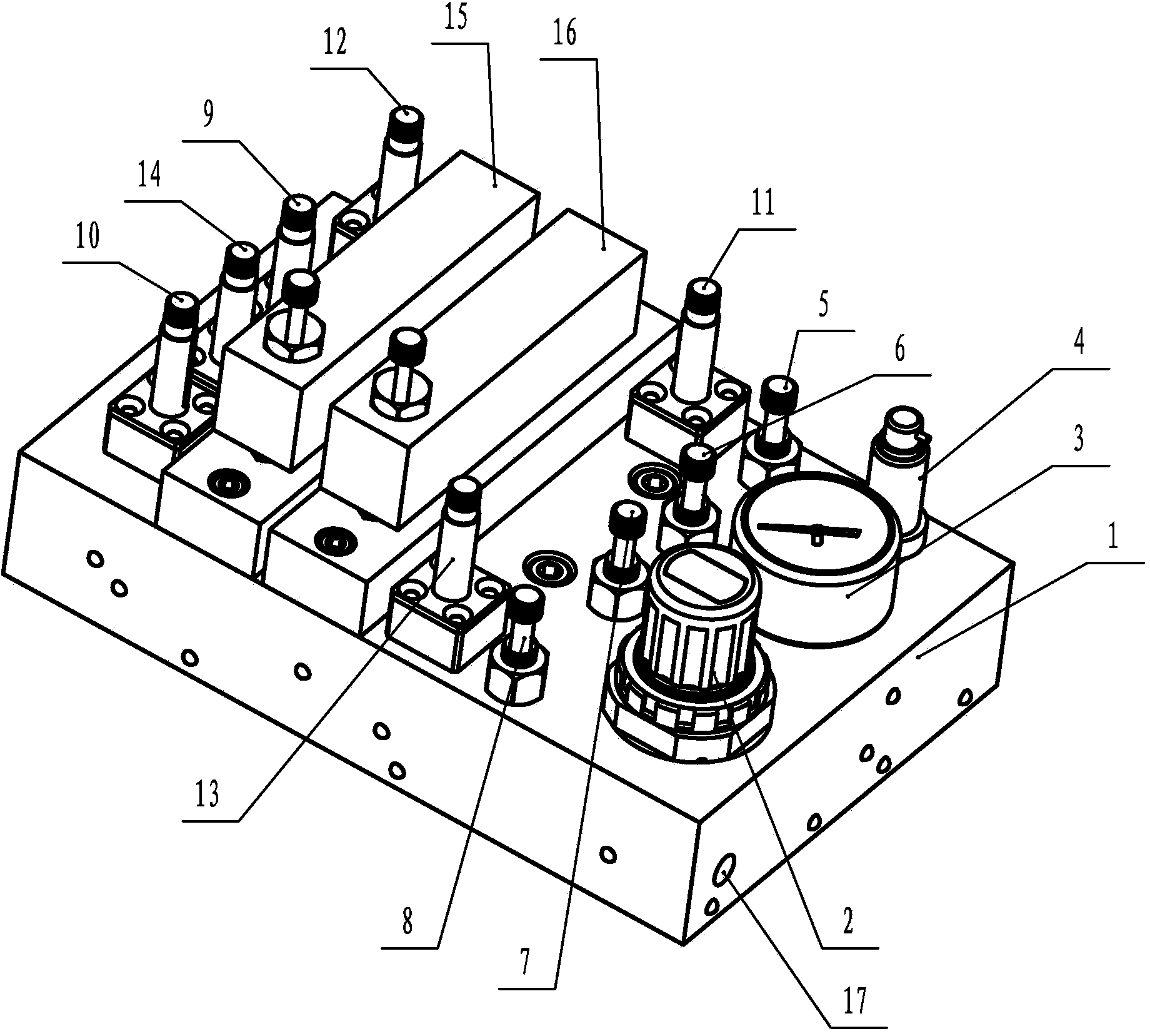
[0018] refer to figure 1 As shown, the gas circuit diagram of the argon excitation system in this embodiment includes: forced blowing gas circuit A, main gas circuit B, side gas circuit C, public gas circuit D, and shutter control gas circuit E.

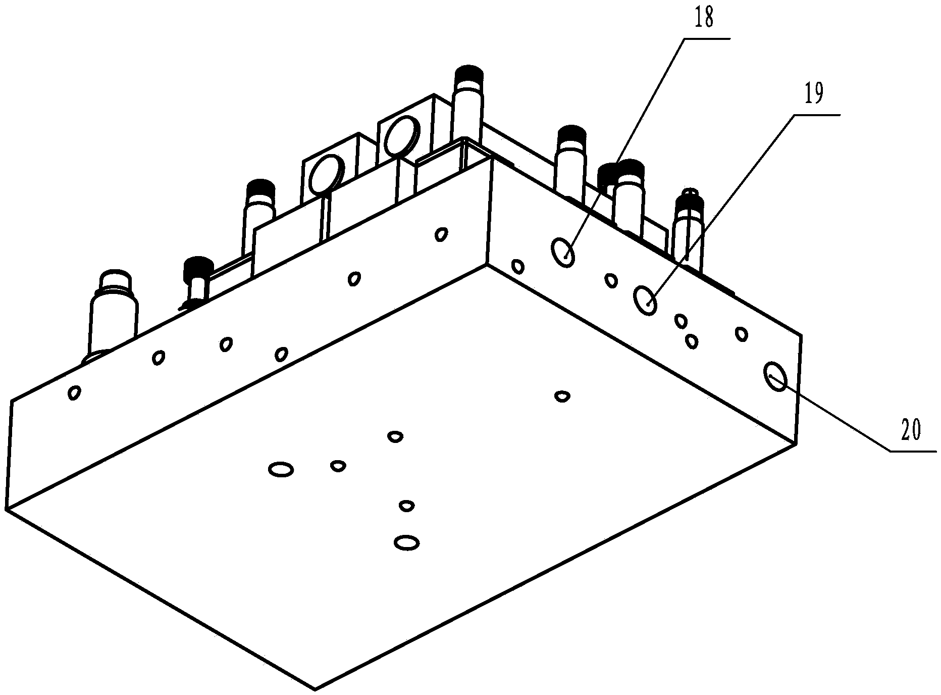
[0019] The airflow input end of the forced blowing air path A is an air source 17, the airflow output end is a first air outlet 18, and a first electromagnetic valve 9 is arranged between the airflow input end and the air flow output end.

[0020] The airflow input end of the public air passage D is the air source 17, the airflow output end is connected to the airflow input end of the shutter control air passage E, and a pressure relief valve 2 and a pressure sensor 4 are arranged between the airflow input end and the airflow output end.

[0021] The main gas path B and the side gas path C are arranged sid...


PUM


Abstract

The invention provides an argon excitation system of a spectrograph. The argon excitation system comprises a strong blowing air channel, a main air channel, a side air channel, a public air channel and a shutter control air channel, wherein all the air channels are arranged on an integrated air channel plate of the argon excitation system of the spectrograph; an air source is arranged at an airstream inlet of the strong blowing air channel, and an airstream outlet of the strong blowing air channel serves as a first air outlet; the air source is arranged at an airstream inlet of the public air channel and is connected with the shutter control air channel, an airstream inlet of the main air channel is formed in the public air channel and is provided with an argon meter, and an airstream outlet of the main air channel serves as the first air outlet; an airstream inlet of the side air channel is formed in the public air channel, and an airstream outlet of the side air channel serves as a second air outlet; the airstream outlet of the shutter control air channel serves as a third air outlet; the air channels are respectively at least provided with an electromagnetic valve. The argon excitation system provided by the invention has the advantages that the pressure is changed, design of different air channels is available, the gas tightness is good, and the precision of the argon excitation system is improved.

Description

technical field [0001] The invention relates to a gas path system, in particular to a gas path system of a spectrometer. Background technique [0002] The photoelectric direct reading spectrometer is an emission spectrometer, which is mainly used to quantitatively analyze the sample by measuring the intensity of the characteristic spectrum representing each element when the sample is excited. At present, both domestic and foreign photoelectric direct reading spectrometers can basically be divided into 4 modules according to their functions. 1. Excitation system: the task is to fully atomize solid samples through various methods and release the emission spectrum light of each element. 2. Optical system: process (organize, separate, screen, capture) complex optical signals generated by the excitation system. 3. Measurement and control system: measure the characteristic spectral line intensity representing each element, and convert the light intensity signal of the spectral li...

Claims


Application Information

Patent Timeline
IPC IPC(8): G01N21/63
Inventor 张乃州赵珍阳邱平高国栋李香宇王世功田中朝许玉兴
Owner YANTAI DONGFANG ANALYTICAL INSTR
Why Eureka
Try Eureka