Open-circuit fault detection method for three-phase inverter with phase-redundant fault-tolerant structure
A three-phase inverter, open-circuit fault technology, applied in the direction of instruments, measuring electricity, measuring devices, etc., can solve the problems of increasing the amount of calculation, increasing the cost, etc., to avoid false alarms, simple algorithms, and tolerance of fluctuations in detection variables. Effect
- Summary
- Abstract
- Description
- Claims
- Application Information
AI Technical Summary
Problems solved by technology
Method used
Image
Examples
Embodiment
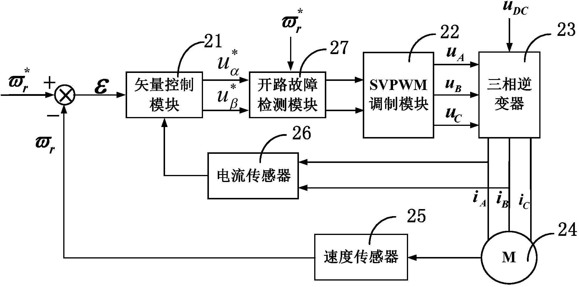
[0054] Figure 4 It is a schematic diagram of an open-circuit fault detection method for a three-phase inverter with a phase redundancy fault-tolerant structure of the present invention. like Figure 4 As shown, the three-phase inverter open-circuit fault detection method of the phase redundancy fault-tolerant structure of the present invention comprises the following steps:
[0055] S1: Obtain the desired voltage from the closed-loop control system of the motor drive system Then Converted to three-phase expected voltage after Clark coordinate transformation
[0056] S2: Calculate the detection variable dn. Different from the prior art, the present invention directly adopts the three-phase expected voltage mean of absolute value To perform normalization processing, so as to eliminate the impact of load changes, the calculation method is:
[0057] d n = u n...
example 1
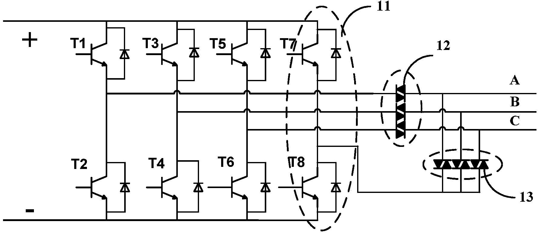
[0083] The rated power of the three-phase AC asynchronous motor is 1.1kW, the rated speed is 1390rpm, the rated torque is 7.6Nm, the rated current is 2.89A, and the load torque is 50% of the rated load. Set detection variable threshold k m =0.08,k d =0.93. Figure 5 is the three-phase current of the motor in Example 1, and the detection variable d n and a n Waveform diagram. like Figure 5 As shown, the three-phase inverter in Example 1 has three faults: when time t=1.6s, T2 has an open circuit fault; when t=1.8s, both T1 and T2 have an open circuit fault; , T2 and T4 simultaneously open circuit fault.
[0084] a)t=1.4~1.6s, such as Figure 5 As shown, the three-phase current of the motor is a symmetrical sine wave, d n ≈0,a n ≈1, the inverter works normally, fault indication D a =D b =D c = 0,A a =A b =A c = H, according to the fault location table 1, it can be seen that there is no open circuit fault of the switching tube, and the three-phase inverter is worki...
example 2
[0089]The rated power of the three-phase AC asynchronous motor is 1.1kW, the rated speed is 1390rpm, the rated torque is 7.6Nm, the rated current is 2.89A, and the load torque is 50% of the rated load. Set detection variable threshold k m =0.08,k d =0.93. Figure 6 is the three-phase current of the motor in Example 2, and the detection variable d n and a n Waveform diagram. like Figure 6 As shown, the three-phase inverter set in Example 1 has three faults: when t=1.6s, T1 has an open circuit fault; when t=1.8s, T1 and T4 have open circuit faults at the same time; T4 and T5 open circuit fault occurred simultaneously.
[0090] e)t=1.4~1.6s, such as Figure 6 As shown, the three-phase current of the motor is a symmetrical sine wave, d n ≈0,a n ≈1, fault indication D a =D b =D c = 0,A a =A b =A c = H, according to the fault location table 1, it can be seen that there is no open circuit fault of the switching tube, and the three-phase inverter is working normally; ...
PUM
 Abstract
Description
Claims
Application Information
 - R&D
- Intellectual Property
- Life Sciences
- Materials
- Tech Scout
- Unparalleled Data Quality
- Higher Quality Content
- 60% Fewer Hallucinations
Browse by: Latest US Patents, China's latest patents, Technical Efficacy Thesaurus, Application Domain, Technology Topic, Popular Technical Reports.
© 2025 PatSnap. All rights reserved.Legal|Privacy policy|Modern Slavery Act Transparency Statement|Sitemap|About US| Contact US: help@patsnap.com


