
Multi-wavelength optical fiber filter

An optical fiber filter, multi-wavelength technology, applied in the field of optical communication, can solve the problems of limited number of channels, the inability of multi-wavelength filters to adapt to dynamic optical communication systems, and technical development limitations.

Inactive Publication Date: 2014-06-18
HUAZHONG UNIV OF SCI & TECH
View PDF8 Cites 7 Cited by
  • Summary
  • Abstract
  • Description
  • Claims
  • Application Information

AI Technical Summary

Problems solved by technology

[0004] The existing multi-wavelength filters with fixed channel frequency spacing cannot adapt to dynamic optical communication systems, so there are many inconveniences in actual use; and the dynamically adjustable multi-wavelength filters can achieve flexible filtering effects, so it is more Meet the actual application needs, so it has become a current research hotspot
Generally, the schemes to realize the adjustable filter include mechanical adjustment, liquid crystal adjustment and adjustment by using the electro-optic effect of the crystal. For the structure of the all-fiber Mach-Zehnder interferometer, thermal tuning is a reliable alternative. It has been reported that a linearly chirped fiber grating is heated by a micro-heating array to realize a switchable, discrete bandpass filter, but the disadvantage of this scheme is that the number of channels is very limited, and its periodicity may not be able to get a good guarantee
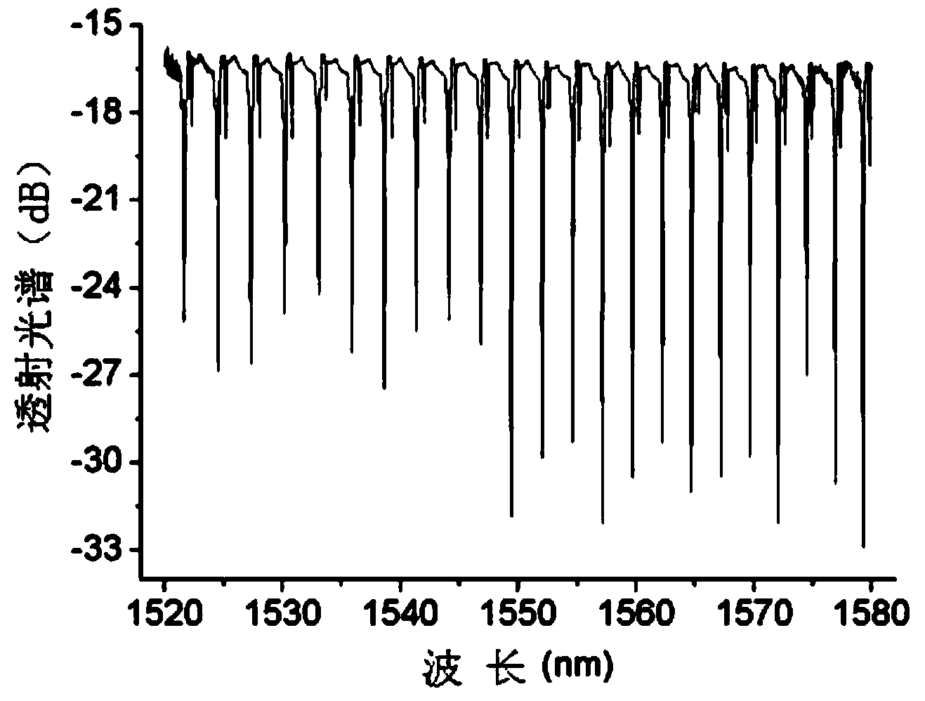
At the same time, a filter with a flat top is desired in practical applications, because it can improve signal fidelity and increase tolerance to signal wavelength drift. Existing technologies cannot achieve both flat transmission peaks and adjustable bandwidth.
[0005] In summary, the existing multi-wavelength filters with fixed channel frequency intervals cannot adapt to dynamic optical communication systems, resulting in limited technological development. Therefore, it is urgent to develop a multi-wavelength filter with a flexible and adjustable free spectral range, and requires its Can achieve a large dynamic range

Method used


Image

  • Multi-wavelength optical fiber filter
  • Multi-wavelength optical fiber filter
  • Multi-wavelength optical fiber filter

Examples


Embodiment Construction

[0019] The following will clearly and completely describe the technical solutions in the embodiments of the present invention with reference to the accompanying drawings in the embodiments of the present invention. Obviously, the described embodiments are only some, not all, embodiments of the present invention. All other embodiments obtained by persons of ordinary skill in the art based on the embodiments of the present invention belong to the protection scope of the present invention.

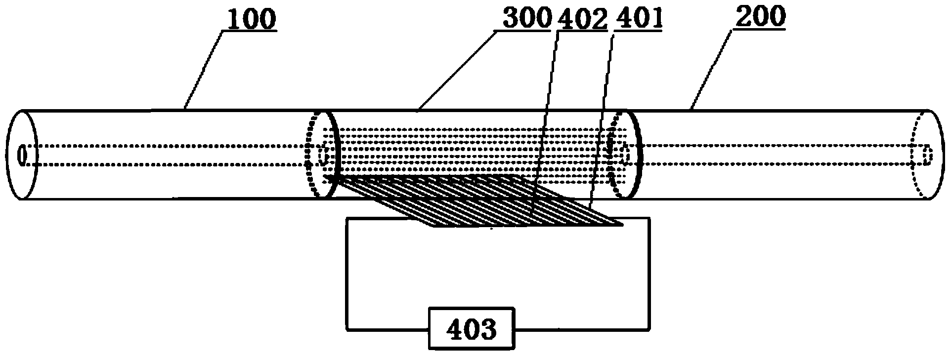
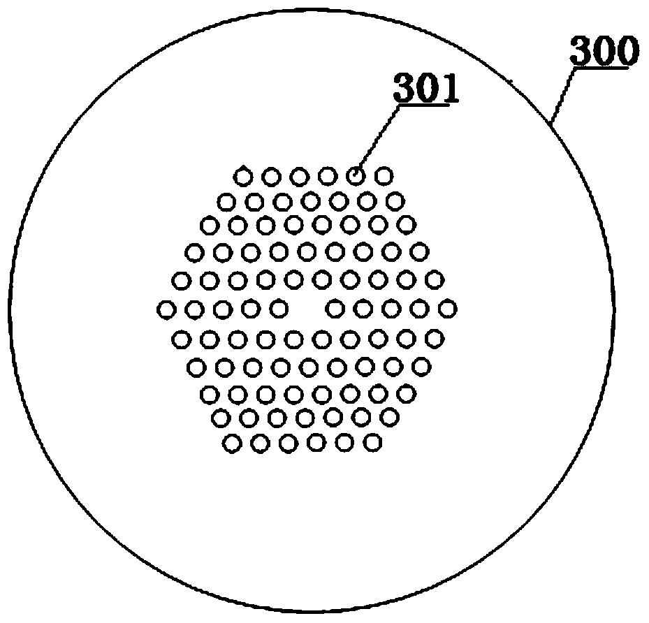
[0020] see figure 1 , a multi-wavelength optical fiber filter provided by an embodiment of the present invention, comprising: a first single-mode optical fiber 100, a second single-mode optical fiber 200, a photonic crystal optical fiber 300, and a temperature control module for heating the photonic crystal optical fiber; wherein , one end of the first single-mode fiber 100 is connected to one end of the photonic crystal fiber 300 for the input of the light beam; one end of the second single-...


PUM


Abstract

The invention discloses a multi-wavelength optical fiber filter, comprising a first single mode optical fiber, a second single mode optical fiber, a photonic crystal optical fiber and a temperature control module; one end of the first single mode optical fiber is connected with one end of the photonic crystal optical fiber for inputting light beams; one end of the second single mode optical fiber is connected with the other end of the photonic crystal optical fiber for outputting the light beams; the temperature control module is attached to the side wall of the photonic crystal optical fiber for regulating and controlling the temperature of the photonic crystal optical fiber and realizing the tuning on the multi-wavelength optical fiber filter in the free-spectrum range; an organic matter layer for enhancing the thermal sensitive property of the photonic crystal optical fiber is filled in air holes of the photonic crystal optical fiber. The multi-wavelength optical fiber filer has the characteristics of flexible and adjustable free spectrum range and flat top of transmitted spectrum.

Description

technical field [0001] The invention belongs to the technical field of optical communication, in particular to a multi-wavelength optical fiber filter. Background technique [0002] Multi-wavelength filters are widely used in wavelength division multiplexing systems, and are mainly used as multi-channel isolation filters and wavelength selection filters. [0003] Commonly used multi-wavelength filter implementations include crystal birefringence, arrayed waveguide gratings, and Mach-Zehnder interferometers, among which the all-fiber Mach-Zehnder interferometer multi-wavelength filter can be well integrated The existing communication system is compatible, and the insertion loss is small, so it has received more attention. [0004] The existing multi-wavelength filters with fixed channel frequency spacing cannot adapt to dynamic optical communication systems, so there are many inconveniences in actual use; and the dynamically adjustable multi-wavelength filters can achieve fl...

Claims


Application Information

Patent Timeline
IPC IPC(8): G02F1/01
Inventor 唐明赵志勇付松年沈平
Owner HUAZHONG UNIV OF SCI & TECH
Learn More