Direct current thermomagnetic release device and method for reducing temperature rise of terminal of the device

A thermal-magnetic release, current technology, applied in the direction of protection switch operation/release mechanism, etc., can solve the problems of terminal temperature rise, reduce the terminal temperature rise of DC thermal-magnetic release, and achieve the effect of reducing the terminal temperature rise

Active Publication Date: 2014-06-18
SCHNEIDER ELECTRIC IND SAS
View PDF6 Cites 3 Cited by
  • Summary
  • Abstract
  • Description
  • Claims
  • Application Information

AI Technical Summary

Problems solved by technology

[0005] The present invention aims to propose a DC thermal-magnetic release device that reduces the temperature rise of terminals and a method for reducing the terminal temperature rise of the above-mentioned DC thermal-magnetic release, which solves the problems of thermal-magnetic releases in the prior art. The technical problem of excessive temperature rise of the device terminals can effectively reduce the terminal temperature rise of the DC thermal magnetic release while ensuring that the thermal performance of the DC thermal magnetic release is not affected

Method used


Image

  • Direct current thermomagnetic release device and method for reducing temperature rise of terminal of the device
  • Direct current thermomagnetic release device and method for reducing temperature rise of terminal of the device
  • Direct current thermomagnetic release device and method for reducing temperature rise of terminal of the device

Examples


Embodiment Construction

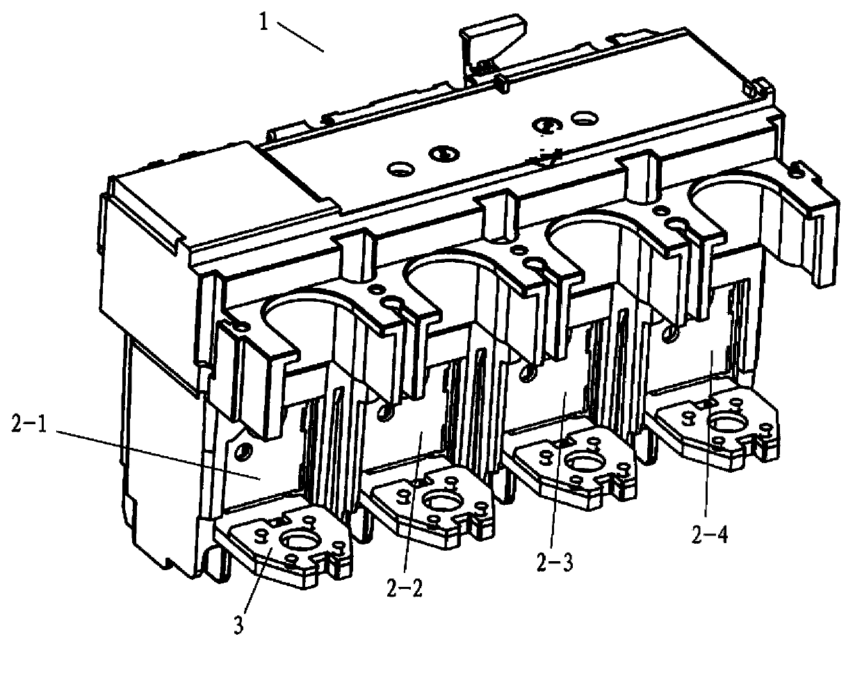
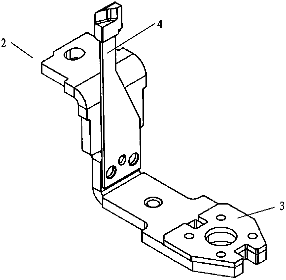
[0040] Refer below Figure 1 to Figure 4-4 The DC thermal-magnetic release device for reducing terminal temperature rise and the method for reducing the terminal temperature rise of the above-mentioned DC thermal-magnetic release are more clearly described.

[0041] figure 1It shows a perspective view of a first embodiment of a DC thermal-magnetic trip device for reducing terminal temperature rise according to the present invention. In this embodiment, the DC thermal-magnetic trip device 1 has a 4-pole heating element 2, One end of the heating element 2 is the terminal 3 . The heating element 2-1 and the heating element 2-3 have the same resistance, the heating element 2-2 and the heating element 2-4 have the same resistance, the two groups of resistances are different from each other, and are divided into high resistance heating elements 2-1, 2-3 and low-resistance heating elements 2-2, 2-4, the 4 heating elements, that is, 4-pole heating elements are connected in series wi...


PUM


Abstract

The invention aims to provide a direct current thermomagnetic release device which reduces a temperature rise of a terminal and the method for reducing the temperature rise of the terminal, and solves the technical problem in the prior art that the temperature rise of the terminal of a thermomagnetic release device is too high. The direct current thermomagnetic release device comprises a plurality of heating elements, the plurality of heating elements are connected in series with a power supply and a load to form a closed loop for current conduction, wherein the plurality of heating elements comprise high-resistance heating elements and low-resistance heating elements, the high-resistance heating elements are used for thermal protection of the thermomagnetic release device, the low-resistance heating elements are used for conducting current, and in the closed loop, the high-resistance heating elements and the low-resistance heating elements are alternately arranged. According to the direct current thermomagnetic release device in the invention, while thermal performance of the direct current thermomangetic release is not affected, the temperature rise of the terminal of the direct current thermomagnetic release can also be effectively reduced.

Description

technical field [0001] The invention relates to a DC thermal-magnetic release device and a method for reducing the temperature rise of its terminals, in particular to a thermal-magnetic release device for a DC circuit breaker and a thermal-magnetic release device for reducing the terminal temperature rise method of terminal temperature rise. Background technique [0002] With the development of new energy, rail transit and communication power supply, the application of DC circuit breakers has become more and more extensive. A large number of new energy project environments also put forward higher requirements for the terminal temperature rise of the DC circuit breaker. The American standard (UL) requires the terminal temperature rise to be <50°C. It is difficult to meet the temperature rise requirements of UL terminals. The protection device of each pole of the traditional DC thermal-magnetic release used in the DC circuit breaker is also equipped with a thermal protect...

Claims


Application Information

Patent Timeline
Patent Type & Authority Applications(China)
IPC IPC(8): H01H71/40
Inventor 黄银芳韩志刚张晋德
Owner SCHNEIDER ELECTRIC IND SAS
Why Eureka
Try Eureka