

A Servo Loop Control System and Control Method for Oil Slick Supporting Inertial Instrument
An inertial instrument and servo loop technology, applied in control systems, AC motor control, electrical components, etc., can solve the problems of inconsistent models, slow heat dissipation, smaller system damping, etc., to achieve a safe and reliable degree of automation, high degree of automation, control high precision effect
Active Publication Date: 2016-05-04
BEIJING INST OF AEROSPACE CONTROL DEVICES
View PDF5 Cites 0 Cited by
- Summary
- Abstract
- Description
- Claims
- Application Information
AI Technical Summary
Problems solved by technology
However, due to the complex application environment of the instrument and slow heat dissipation, the actual stable temperature of the oil slick is likely to be higher than the preset temperature point. The increase in the temperature of the oil slick will cause the system damping to become smaller, so that the servo loop design correction network does not match the actual application object model, and the system The stability margin becomes smaller
Method used
View moreImage
Smart ImageViewing Examples

Examples
Embodiment
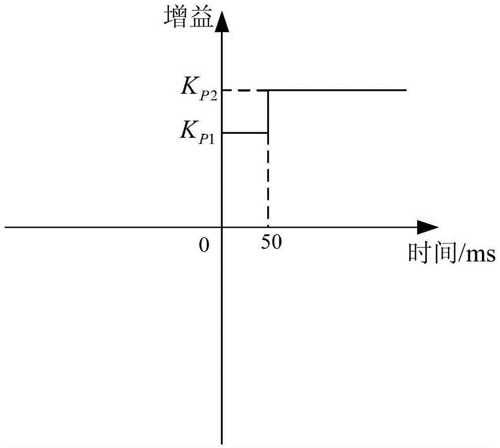
[0024] A set of gyro accelerometer design parameters are given below, and the thresholds of the above temperature points are T 1 =54℃, T 2 =56℃, T 3 =58℃, T 4 =60℃; the corresponding gain within the threshold is K H =4.0,K M =3.5,K L =3.2, the measured system stability margins all meet the design requirements of amplitude margin>10dB and phase angle margin>40 degrees. K P1 is 3.0.
Login to View More PUM
 Abstract
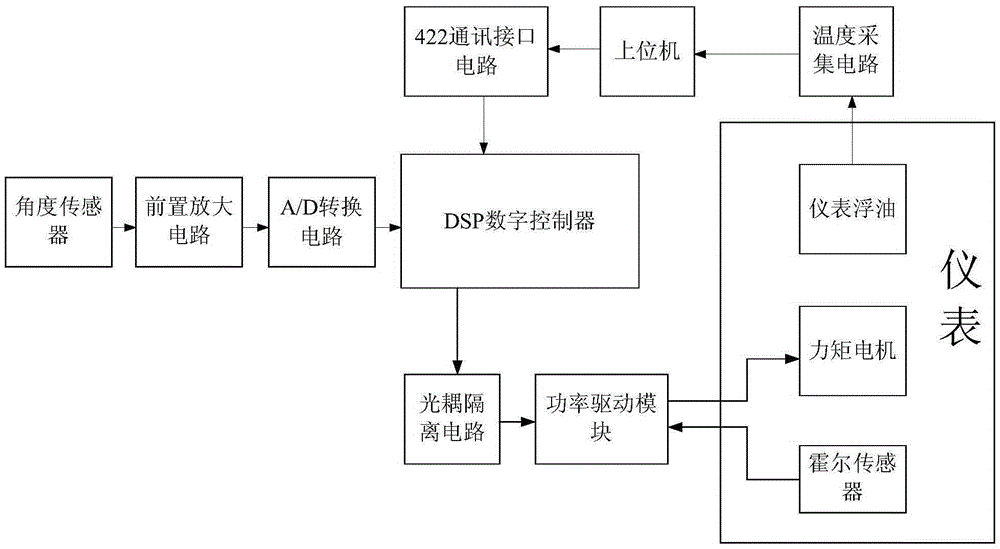
The invention discloses a servo loop control system and control method for a floating oil support inertia instrument. The control system mainly comprises an angle sensor, a front positioned amplification circuit, an A / D (analog / digital) conversion circuit, a DSP (digital signal processor) digital controller, a photocoupling isolation circuit, a power driving module, a moment motor, a hall sensor, a 422 communication interface circuit, a temperature collection circuit and an upper computer. The nonlinear control in the starting stage of the control system and the temperature gradient precise control of an instrument servo loop are respectively realized by introducing a variable parameter correction network DSP digital controller. The upper computer collects the floating oil temperature information in the instrument by the temperature collection circuit and sends the information to the DSP digital controller by the 422 communication interface circuit. The DSP digital controller compares the temperature with a given temperature threshold value and calls corresponding control parameters, so the variable parameter servo control for different temperatures of the instrument is realized. The control system is high in integration degree, high in control precision, high in automation degree, safe and reliable.
Description
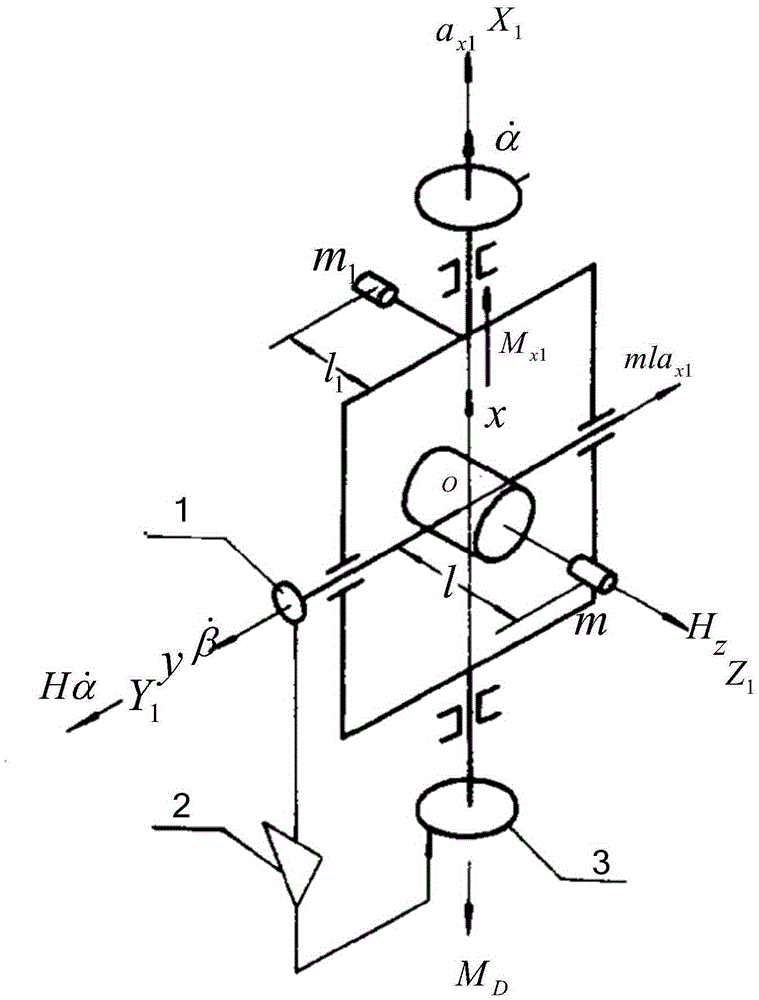
technical field [0001] The invention relates to a servo loop control system and a control method for an inertial instrument supported by slick oil. Background technique [0002] Taking the gyro accelerometer as an example, the principle of the oil slick supporting the inertial instrument is explained below. Such as figure 1 As shown, the outer ring coordinate system of the gyro accelerometer is OX 1 Y 1 Z 1 ,OX 1 is the axis of the outer frame, OY 1 is the axis of the inner frame, OZ 1 is the angular momentum direction of the motor, , are the angular velocities of the outer frame relative to the instrument base and the inner frame relative to the outer frame, respectively, M X1 is the sum of various disturbance moments around the outer frame axis, M D Torque generated by the torque motor. The shaft of the inner frame is supported by slick oil. Due to the disturbance moment M on the axis of the outer frame X1 influence, the angular momentum H will slowly move t...
Claims
Login to View More Application Information
Patent Timeline
 Patent Type & AuthorityPatents(China)
IPC IPC(8): H02P23/00G01C21/16
Inventor章丽蕾严小军张沛晗岳辉杨志超周敏
OwnerBEIJING INST OF AEROSPACE CONTROL DEVICES