
Triangle wave signal generation method and triangle wave generator

A technology of signal generator and triangular wave, which is applied in the direction of pulse generation, electrical components, pulse technology, etc., can solve the problems of lack of reach, large symmetry of triangular wave, and low resolution of triangular wave

Active Publication Date: 2014-06-18
RIGOL
View PDF4 Cites 6 Cited by
  • Summary
  • Abstract
  • Description
  • Claims
  • Application Information

AI Technical Summary

Problems solved by technology

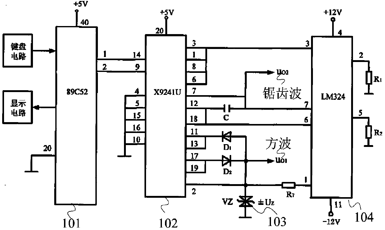
[0007] (1) The integrating circuit is composed of an operational amplifier and a number of resistors and capacitors. Due to the influence of non-ideal factors such as the limited gain, bandwidth and swing of the operational amplifier, as well as the thermal noise and process mismatch introduced by the resistors and capacitors, the integrating circuit is difficult. Generate high-performance triangular wave signals with good linearity and large signal distortion;
[0008] (2) The resistance taps of the variable resistor of the digital potentiometer X9241U are 64, and the limited number of taps results in low resolution of the symmetry of the triangular wave;
[0009] (3) The resistance range of the variable resistor of the digital potentiometer X9241U is 2KΩ to 50KΩ, that is, the symmetry of the generated triangular wave is up to 96%, and it cannot reach 100%.
Especially when the symmetry of the triangular wave is 100% or 0%, more harmonic components will be generated, which will affect the test effect of the triangular wave signal generator

Method used


Image

  • Triangle wave signal generation method and triangle wave generator
  • Triangle wave signal generation method and triangle wave generator
  • Triangle wave signal generation method and triangle wave generator

Examples


Embodiment 1

[0211] In this embodiment, an FPGA is used as a triangular wave generating unit to generate a triangular wave signal. Such as Figure 8 As shown, it is a functional block diagram of the triangular wave generating unit in the embodiment to generate the triangular wave signal. It includes: a processor interface 801 , a phase accumulator 802 , a comparator 803 , a selector 804 and a multiplier 805 . The basic principle of the present invention is: the phase accumulator generates periodic counting, that is, the phase code; the comparator compares the time threshold and the phase code; selects an amplitude coefficient and multiplies the phase code according to the comparison result, and within the rising edge time, uses the rising edge amplitude The coefficient is multiplied by the phase code, and within the falling edge time, the falling edge amplitude coefficient is multiplied by the phase code; the product is a triangle wave signal in digital form.

[0212] Depend on Figure ...


PUM


Abstract

The invention relates to a triangle wave signal generation method and a triangle wave generator. The generator comprises a triangle wave parameter processing unit and a triangle wave generating unit. The triangle wave parameter processing unit is used to process triangle wave parameters to obtain a frequency control word, a time threshold, and an amplitude coefficient. The triangle wave generating unit is used to generate a triangle wave signal according to information obtained by the triangle wave parameter processing unit. The triangle wave generating unit comprises: a phase accumulating module for accumulating the frequency control word once on a rising edge of a clock pulse TC of the triangle wave generating unit to generate a phase code; a comparison module for comparing the phase code and the time threshold obtained by the triangle wave parameter processing unit to generate a triangle wave mark; a selection module determining an output rising edge amplitude coefficient or a falling edge amplitude coefficient in a complement form in a time period according to the triangle wave mark generated by the comparison module; and a multiplication module obtaining the triangle wave signal based on the phase code and the amplitude coefficient output by the selection module.

Description

technical field [0001] The invention relates to the technical field of test and measurement, in particular to a method for generating a triangular wave signal and a triangular wave generator. Background technique [0002] The invention belongs to the technical field of test and measurement, and in particular relates to a method for generating a triangular wave signal. [0003] In the field of test and measurement, a triangular wave signal generator for generating a triangular wave is widely used. For example, electronic equipment in the fields of radar and communication needs a triangular wave signal with good linearity as a modulation signal or a reference signal. In a Class D audio power amplifier modulated by PWM, the triangular wave is used as an analog signal to be converted into a pulse signal. [0004] The main time-domain parameters of the triangle wave signal include amplitude, period, linearity, symmetry, etc. The linearity refers to the degree to which the edge ...

Claims


Application Information

Patent Timeline
IPC IPC(8): H03K4/06
Inventor 丁新宇王悦王铁军李维森
Owner RIGOL
Learn More