
3d endoscope device

An endoscope and three-dimensional technology, which is applied in the field of three-dimensional endoscope devices, can solve problems such as image quality degradation

Active Publication Date: 2014-06-18
OLYMPUS CORP
View PDF10 Cites 15 Cited by
  • Summary
  • Abstract
  • Description
  • Claims
  • Application Information

AI Technical Summary

Problems solved by technology

Therefore, in the method of imaging on the area obtained by dividing the light-receiving surface of the nearly square image sensor into left and right, the image must be enlarged in the horizontal direction at a large magnification afterward, which is a cause of deterioration in image quality.

Method used


Image

  • 3d endoscope device
  • 3d endoscope device
  • 3d endoscope device

Examples


Embodiment Construction

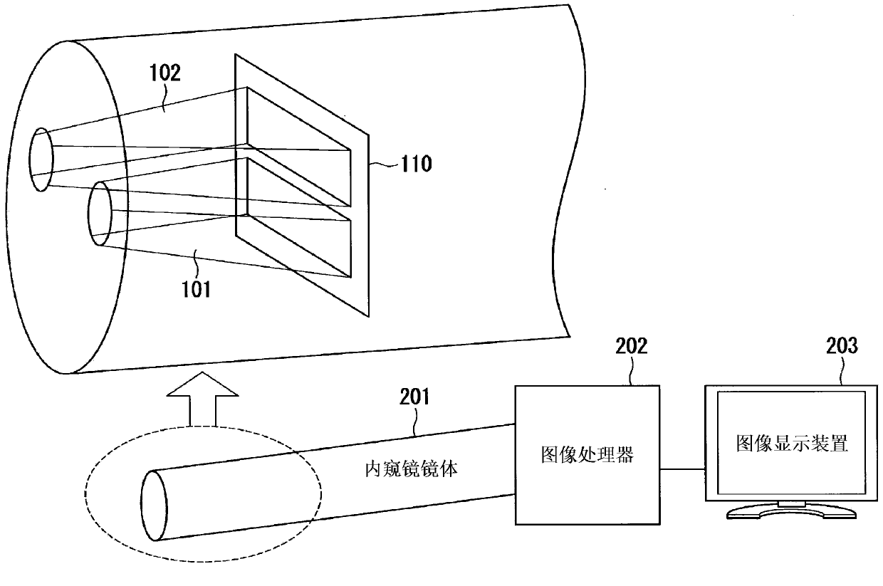
[0030] Embodiments of the present invention will be described below with reference to the drawings. figure 1 A schematic configuration of a three-dimensional endoscope device according to one embodiment of the present invention is shown. refer to figure 1 A three-dimensional endoscope device will be briefly described.

[0031] The three-dimensional endoscope device has: an endoscope body 201 having an optical system 101 for a left eye, an optical system 102 for a right eye, a CMOS sensor 110 (MOS type sensor); an image processor 202; an image display as a monitor device 203 . The left-eye optical system 101 , the right-eye optical system 102 , and the CMOS sensor 110 are arranged at the front end of an endoscope scope 201 .

[0032] The left-eye optical system 101 and the right-eye optical system 102 are two-system optical systems that image light corresponding to a left-eye image and a right-eye image, respectively. The left-eye optical system 101 and the right-eye opti...


PUM


Abstract

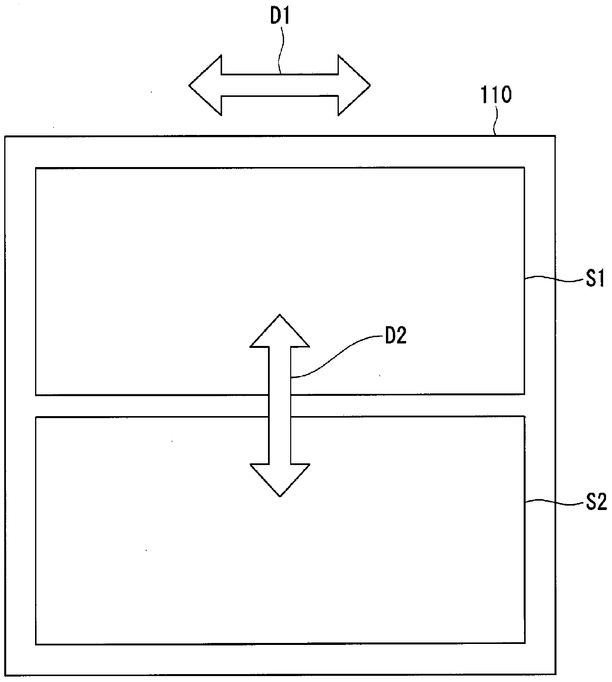
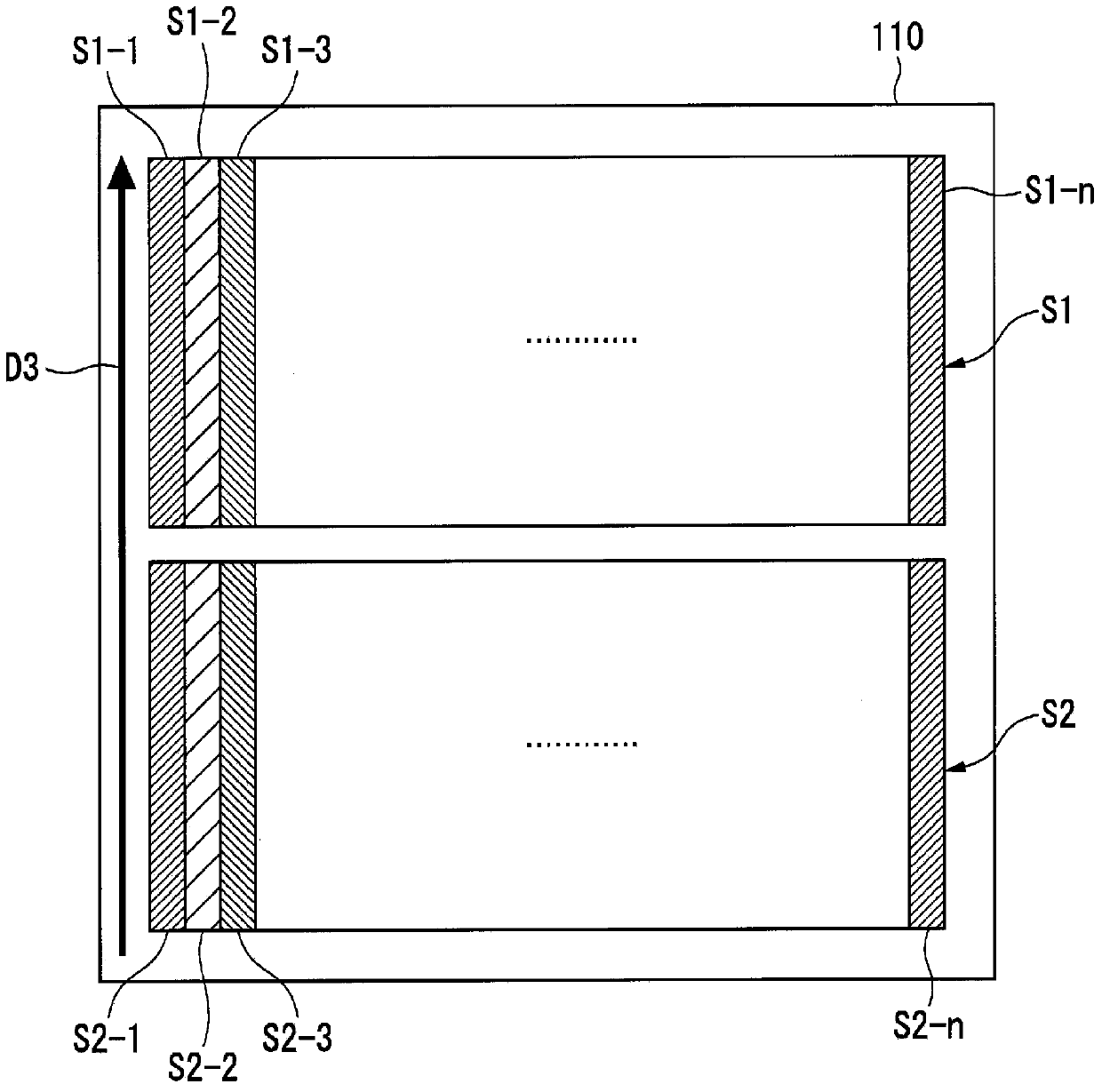
In the present invention, an endoscope scope is provided with a left-eye optical system and a right-eye optical system that form an image with light corresponding to a left-eye image and a right-eye image, and is provided with a CMOS sensor on which first light and second light obtained through the left-eye optical system and the right-eye optical system are formed into separate images on a single light receiving surface. A straight line that connects the center of a first image and the center of a second image formed on the light receiving surface of the CMOS sensor is orthogonal to the parallax direction. On the light receiving surface of the CMOS sensor, a first region in which the center of the first image and the second image are formed is divided into a plurality of first divided regions, and a second region is divided into a plurality of second divided regions. When the CMOS sensor reads data constituting image signals from the first region and the second region, the CMOS sensor reads data by alternating scanning a first divided region at a position corresponding to the left-eye image and a second divided region at a position corresponding to the right-eye image.

Description

technical field [0001] The present invention relates to a three-dimensional endoscope device for imaging left-eye / right-eye images on a single MOS sensor. [0002] This application claims priority based on Japanese Patent Application No. 2011-226756 for which it applied in Japan on October 14, 2011, and uses the content here. Background technique [0003] There is a three-dimensional endoscope device that realizes stereoscopic vision by imaging left-eye / right-eye images with parallax on a single MOS sensor. Due to the installation space of the scope of the endoscope, it is more preferable to use a single image pickup element whose light receiving surface has a shape close to a square to form a left-eye / right-eye image rather than a plurality of image pickup elements. [0004] When forming an image for the left eye and an image for the right eye on a single imaging element, they are usually formed on areas obtained by dividing the light receiving surface of the imaging eleme...

Claims


Application Information

Patent Timeline
Patent Type & Authority Applications(China)
IPC IPC(8): H04N13/02A61B1/04G02B23/24
CPCG02B23/2415H04N13/0207H04N2005/2255A61B1/00193A61B1/00009A61B1/045A61B1/000095A61B1/00194H04N13/207H04N13/00H04N23/555
Inventor 西村久
Owner OLYMPUS CORP
Learn More