In-wheel Motor Assembly

An in-wheel motor and assembly technology, applied in the direction of motion deposition, control devices, power devices, etc., can solve the problems of inability to use wheels in the in-wheel motor system, cost rise, etc., to achieve easy maintenance and management, increase the degree of freedom, and improve The effect of fuel efficiency

Active Publication Date: 2014-06-25
HYUNDAI MOBIS CO LTD
View PDF5 Cites 9 Cited by
  • Summary
  • Abstract
  • Description
  • Claims
  • Application Information

AI Technical Summary

Problems solved by technology

This requires the production and installation of a special wheel hub that matches the in-wheel motor system, and there is a problem that the existing wheel cannot be used for the in-wheel motor system.
In addition, since the torque is increased by the second deceleration of the planetary gear, there is a problem of increasing the capacity of the planetary gear with a complex structure. At the same time, in order to ensure sufficient structural rigidity, the width, outer diameter, etc. should be designed become larger, so it will also become a factor that leads to an increase in cost

Method used


Image

  • In-wheel Motor Assembly
  • In-wheel Motor Assembly
  • In-wheel Motor Assembly

Examples


Embodiment Construction

[0020] Embodiments of the present invention will be described below with reference to the drawings. However, it should be pointed out that the following examples are provided to help understand the present invention, and the scope of the present invention is not limited to the following examples. In addition, the following embodiments are provided to more completely explain the present invention to those skilled in the art, and detailed descriptions of known structures that are judged to unnecessarily obscure the technical gist of the present invention are omitted.

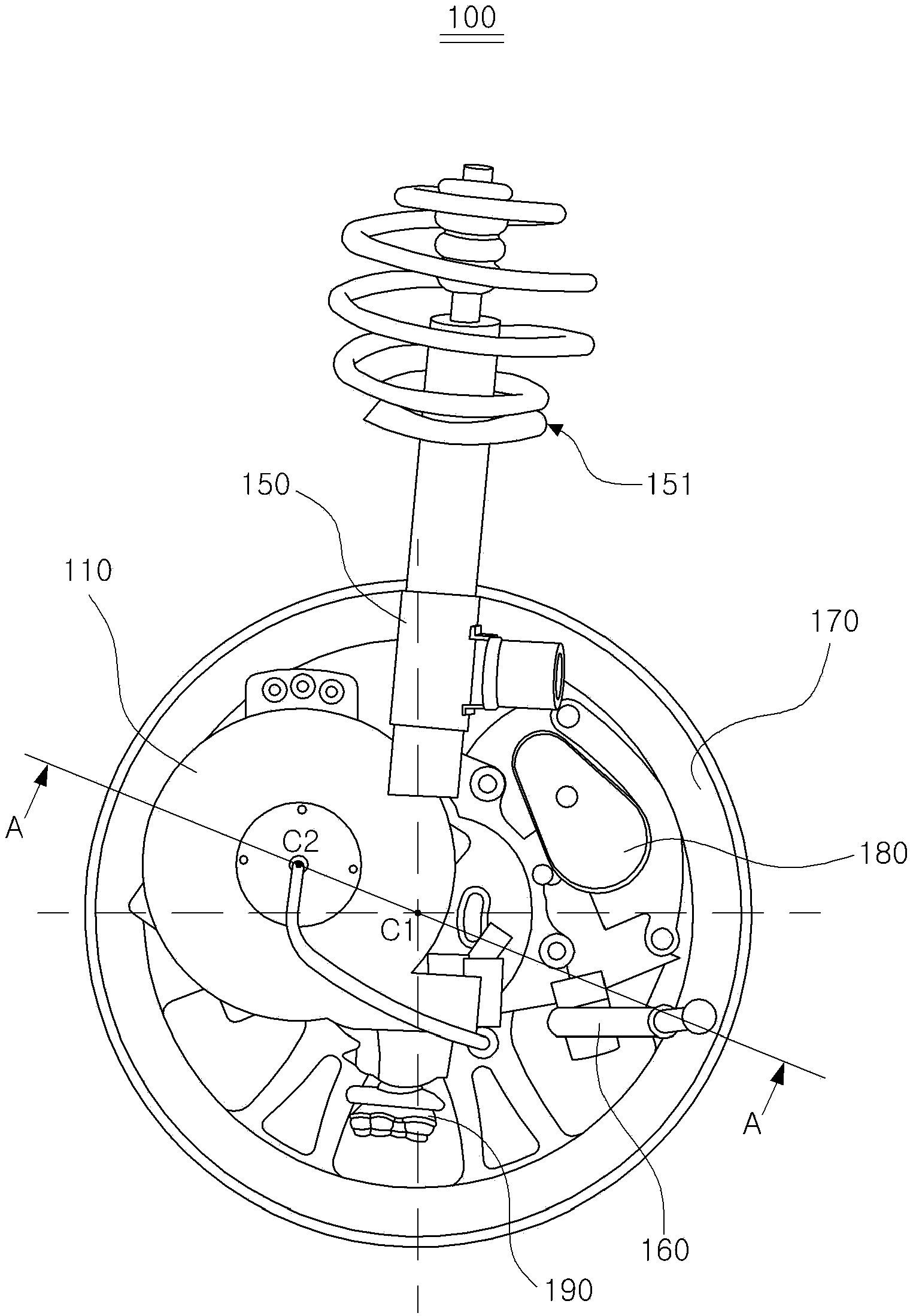
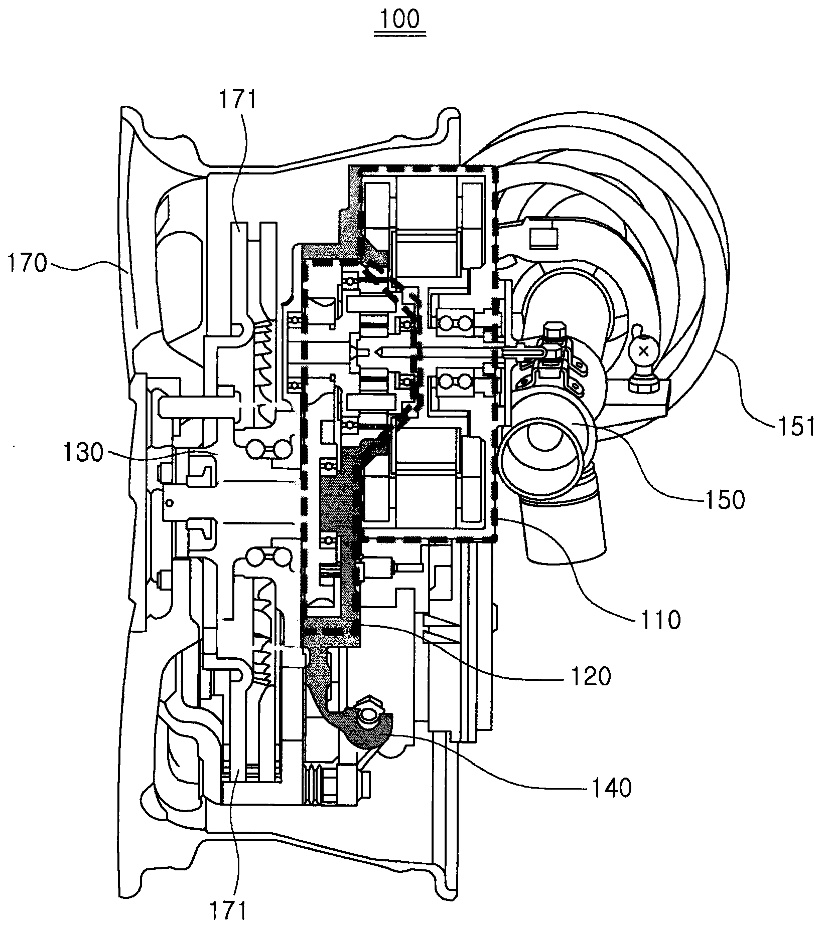
[0021] figure 1 is a configuration diagram of an in-wheel motor assembly according to an embodiment of the present invention.

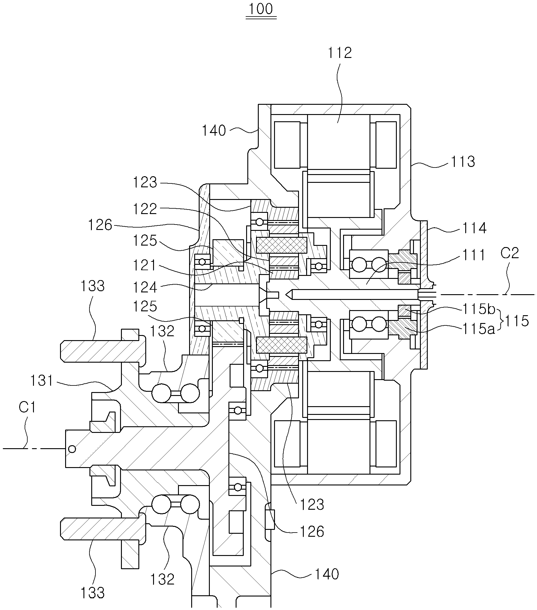
[0022] Such as figure 1 As shown, in terms of the in-wheel motor assembly 100 of this embodiment, the rotation axis C2 of the motor assembly 110 and the rotation axis C1 of the wheel 170 or axle can be disposed at different positions. That is, the rotation axis C2 of the motor assembly...


PUM


Abstract

The present invention provides a motor assembly, including: the motor assembly, its stator and rotor, rotary driving force;Reducer assembly, its has the planetary gear set and the reverse gear set, among them, the planetary gear set described a driving force for the rotation of the motor assembly described for the first time to slow down or increase torque, described in the reverse gear set connected to the planetary gear set described a driving force for the rotation of the motor assembly described in the second deceleration;Wheel hub assembly, gear reducer assembly connection with the stated, put in the reducer assembly of reduction or increase torque rotary driving force transmitted to the wheels of the vehicle, and has described with different rotor axis of rotation for the center of the wheel hub inner ring and accommodate stated wheel outer circle and the fixed support;And the steering knuckle artifacts, described the motor assembly, described in the reducer assembly of fixed support, and described the wheel hub assembly through the support bar and lower arm in the body.

Description

technical field [0001] The invention relates to an in-wheel motor assembly, in particular to an in-wheel motor assembly capable of driving a vehicle through a motor arranged inside a wheel. Background technique [0002] In-wheel motor system (In-wheel motor system) does not use a large single motor in electric vehicles, plug-in hybrid cars, fuel cell vehicles, etc., which use electric energy as the main power source. Rather, it is a system in which motors are separately installed in the wheels to perform decentralized control, and the inside of the wheels is composed of an integrated system such as drive motors, brakes, bearings, and speed reducers. Compared with the system driven by a large-capacity motor, the in-wheel motor system has technical advantages such as high energy efficiency, easy configuration of an electric four-wheel drive system, and improved vehicle driving stability by independently driving and controlling the left and right wheels. [0003] Generally spe...

Claims


Application Information

Patent Timeline
Patent Type & Authority Applications(China)
IPC IPC(8): B60K7/00
CPCB60K7/0007B60K17/046
Inventor 金东铉
Owner HYUNDAI MOBIS CO LTD
Why Eureka
Try Eureka