Plating solution for high-speed electrotinning
A high-speed electroplating and plating solution technology, which is applied in the field of electrochemical deposition of metals and alloys, can solve the problems of environmental pollution in production workshops, increase production costs, and environmental unfriendliness, and achieve excellent dispersion and deep plating capabilities, simple sewage treatment, and satisfactory The effect of technical requirements
Active Publication Date: 2014-06-25
HARBIN INST OF TECH
View PDF11 Cites 17 Cited by
- Summary
- Abstract
- Description
- Claims
- Application Information
AI Technical Summary
Benefits of technology
This patented technology provides new types of materials that are useful when making thin coatings on metal surfaces such as steel or copper. These compositions include certain polymerizable monomers called NMPS, polyglycidol ethyneoxane, pentaerythritol tetrakis(pivalo) acid), trimellurate esters, hydroxyacrylamides, ureidones, iminodazoles, pyridinecarboxallium salts, quaternary nitrogen bases, thioureas, dithionimiazole, diaminopyrimonan, triphenols, etc., all being effective antifriction agents against wear particles from bearings during high speeds. Additionally, these added ingredients have improved dispersibility properties compared to existing antiwear agents like naphtha oil, silica gel, calcium carbonates, zinc stearns, titania powder, silver flakes, magnetic nanopowders, graphite, vanadium dioxide, among others.
Problems solved by technology
This patented technical problem addressed in this patents relates to improving the quality and productivity of industrialized tin plater processes due to increasing demand for higher speeds while reducing environmental concerns associated with existing methods involving tin plasma technology. Current methods involve adding expensive materials like lead scavengers and antiquities during operation, leading to increased cost and waste disposals. There have emerged new technologies called metalloelectrospray deposition ("MJED"), including improved copper plating techniques based upon electrical spray guns. However, these improvements require precise control over particle size distribution, surface properties, and purity levels, making them difficult to achieve without sacrificial agents added.
Method used
View moreImage
Smart ImageViewing Examples
Examples
Embodiment 1
[0039]
Embodiment 2
[0041]
Embodiment 3
[0043]
[0044]
Login to View More PUM
| Property | Measurement | Unit |
|---|---|---|
| Limiting current density | aaaaa | aaaaa |
Abstract
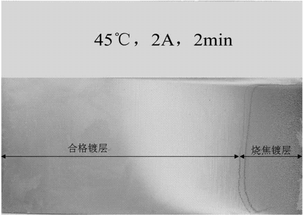
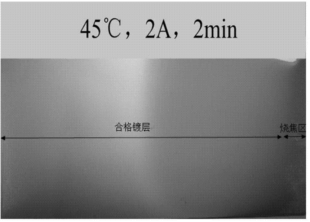
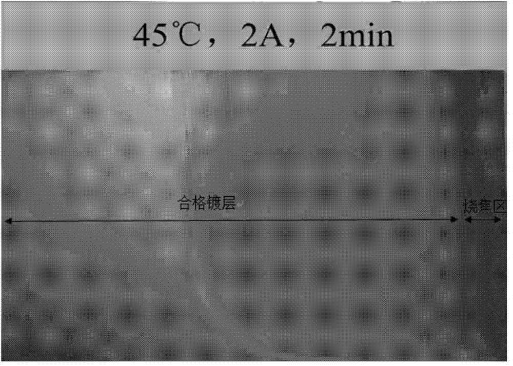
The invention discloses a plating solution for high-speed electrotinning. The plating solution includes the following components: 5-100 g/L tin methanesulfonate, 10-100 ml/L methanesulfonic acid, 0.1-20 ml/L sulfuric acid, 0.1-200 mg/L defoaming agent, 0.1-50 g/L fine grained agent, 0.01-20 g/L change agent and 0.1-40 g/L antioxidant. The plating solution disclosed by the invention has excellent dispersion and deep plating capacity, can meet various technical requirements of a high-speed electrotinning production line, and meanwhile can further reduce the tinning amount (about 0.7 g/m<2>) to save resources, in addition, the highest tolerance limit contents of iron ions and chloride ions of the plating solution are respectively 20 g/L and 1000 ppm. The plating solution disclosed by the invention is more stable than a plating solution without fine grained agent, and after the plating solution is used or placed for several weeks, a good clad layer can still be obtained.
Description
Login to View More Claims
Login to View More Application Information
Patent Timeline
 Owner HARBIN INST OF TECH
Features
- R&D
- Intellectual Property
- Life Sciences
- Materials
- Tech Scout
- Unparalleled Data Quality
- Higher Quality Content
- 60% Fewer Hallucinations
Learn More Browse by: Latest US Patents, China's latest patents, Technical Efficacy Thesaurus, Application Domain, Technology Topic, Popular Technical Reports.
© 2025 PatSnap. All rights reserved.Legal|Privacy policy|Modern Slavery Act Transparency Statement|Sitemap|About US| Contact US: help@patsnap.com


