A pipe string type cementing slurry rapid solidification device

A technology of cementing cement slurry and pipe string, which is applied in the direction of wellbore/well components, earthwork drilling, sealing/isolation, etc., and can solve problems such as erosion, pollution, and stratum engineering construction hazards, which have not been paid attention to and solved. Achieve the effect of improving the cementing quality and changing the liquid column structure

Active Publication Date: 2016-07-06
通奥检测集团股份有限公司
View PDF9 Cites 0 Cited by
  • Summary
  • Abstract
  • Description
  • Claims
  • Application Information

AI Technical Summary

Problems solved by technology

In the cement sealing section, because the specific gravity of water is lower than the formation pressure, the formation fluid can easily enter the wellbore, making the oil, gas and water stored in different layers communicate with each other and flow together, resulting in the interaction between the water layer and the oil and gas layers. Erosion, pollution, at the same time, the cementing effect is greatly reduced
In some wells, high-pressure oil, gas and water in the formation even entered the wellbore and wellhead, pushing up the wellhead device, resulting in a phenomenon of loss of control
[0004] Since most of the above phenomena occur in the underground, they cannot be directly controlled and treated, and cause relatively great harm to the formation, wellhead, and engineering construction. Since the birth of the petroleum development project, this phenomenon has not been paid attention to and resolved.

Method used


Image

  • A pipe string type cementing slurry rapid solidification device

Examples


Embodiment Construction

[0020] The present invention will be described in further detail below in conjunction with specific examples, but not as a limitation of the present invention.

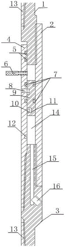
[0021] Such as figure 1 As shown, it is a schematic diagram of a string-type well cementing cement slurry rapid solidification device according to an embodiment of the present invention. It includes an upper joint 1, a lower joint 3, an outer pipe 2, and an inner pipe 4; the upper joint 1 and the lower joint 3 are respectively sealed and connected with the outer pipe 2 (the upper joint and the lower joint are respectively connected with the outer pipe by thread sealing , or through welding and sealing connection.); the inner tube 4 is fixedly installed inside the outer tube 4, and is located between the upper joint 1 and the lower joint 3, and the upper joint 1, the lower joint 3, the outer tube 2 and the inner tube 4 form an airtight space Cavity 14. exist figure 1 In the embodiment shown, the diameter of the oute...


PUM


Abstract

The invention discloses a tubular column type fast well fixing cement paste solidifying device. The tubular column type fast well fixing cement paste solidifying device comprises an upper connector, a lower connector, an outer tube, an inner tube, a hollow shielding bolt, an annular piston and a positioning pin. A closed cavity is formed by the upper connector, the lower connector, the outer tube and the inner tube. An inner cavity of the hollow shielding bolt only penetrates through one end of the hollow shielding bolt, and the hollow shielding bolt is screwed on the inner tube to enable the inner cavity of the hollow shielding bolt to be communicated with the closed cavity. The annular piston is installed in the closed cavity. The positioning pin is respectively inserted into the inner tube and the annular piston. The lower connector is provided with a channel communicated with the closed cavity, and the outlet of the channel is provided with a blocking nut. The tubular column type fast well fixing cement paste solidifying device can inject a liquid accelerator into cement inside a well when the liquid accelerator is needed, and the cement can be solidified within five minutes, the stratum pressing leaking and weightlessness damaging are avoided, the well solidifying quality is further improved, and the purpose of protecting oil, gas, a water layer and underground resources is achieved.

Description

technical field [0001] The invention belongs to the technical field of petroleum exploitation, in particular to a pipe column type cementing cement slurry rapid solidification device. Background technique [0002] In the oil well cementing process of oil exploitation, after cement powder is mixed with water, it is injected into the downhole casing through a hydraulic pump in a liquid state, and then injects mud into the casing, and the cement slurry is squeezed out from the lower part of the casing and rises upward to replace the mud. , fill the annular space, and after solidification, form a solid cement stone, seal the underground formation, and consolidate the casing and the formation as a whole. After well washing, perforating, acidizing, and fracturing, oil and gas channels are established, so that crude oil and natural gas in the formation (oil layer) enter the casing and flow to the ground. [0003] The proportion of cement mixed with water is generally between 1.8 a...

Claims


Application Information

Patent Timeline
Patent Type & Authority Patents(China)
IPC IPC(8): E21B33/13
Inventor 路志武
Owner 通奥检测集团股份有限公司
Why Eureka
Try Eureka