A bottom-hole cementing slurry rapid solidification device

A technology of cementing cement slurry and outer pipe, which is applied in wellbore/well components, earthwork drilling, sealing/isolation, etc., which can solve problems such as erosion, pollution, loss of control, and entry, and achieve the effect of improving cementing quality

Active Publication Date: 2017-01-11
通奥检测集团股份有限公司
View PDF6 Cites 0 Cited by
  • Summary
  • Abstract
  • Description
  • Claims
  • Application Information

AI Technical Summary

Problems solved by technology

In the cement sealing section, because the specific gravity of water is lower than the formation pressure, the formation fluid can easily enter the wellbore, making the oil, gas and water stored in different layers communicate with each other and flow together, resulting in the interaction between the water layer and the oil and gas layers. Erosion, pollution, at the same time, the cementing effect is greatly reduced
In some wells, high-pressure oil, gas and water in the formation even entered the wellbore and wellhead, pushing up the wellhead device, resulting in a phenomenon of loss of control
[0004] Since most of the above phenomena occur in the underground, they cannot be directly controlled and treated, and cause relatively great harm to the formation, wellhead, and engineering construction. Since the birth of the petroleum development project, this phenomenon has not been paid attention to and resolved.

Method used


Image

  • A bottom-hole cementing slurry rapid solidification device
  • A bottom-hole cementing slurry rapid solidification device
  • A bottom-hole cementing slurry rapid solidification device

Examples


Embodiment Construction

[0025] The present invention will be described in further detail below in conjunction with specific examples, but not as a limitation of the present invention.

[0026] Such as Figure 4 As shown, it is a schematic diagram of a rubber plug; the rubber plug 9 includes: a rubber plug iron core 94 , a rubber skirt 92 covers the upper end of the rubber plug iron core 94 , and a flange 96 is provided at the lower end of the rubber plug iron core.

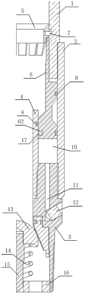
[0027] Such as figure 1 As shown, it is an overall schematic diagram of a bottom-hole cementing slurry rapid solidification device according to an embodiment of the present invention. It includes an upper joint 1, a lower joint 3, an outer pipe 2, and an inner pipe 4; the upper joint 1 and the lower joint 3 are respectively sealed and connected with the outer pipe 2 (the upper joint and the lower joint are respectively sealed with the outer pipe by threads) connected, or sealed by welding.); One end of the inner tube 4 is fixedly insta...


PUM


Abstract

The invention discloses a downhole type well fixing cement slurry rapid solidification device. The device comprises an upper joint, a lower joint, an outer tube, an inner tube, a self-locking grabbing sleeve and a piston; the upper joint, the outer tube and the inner tube form a piston containing space; the outer wall of the lower portion of the self-locking grabbing sleeve is provided with self-locking grabbing threads, the upper end of the self-locking grabbing sleeve is provided with a guide groove along the upper edge, the lower end of the self-locking grabbing sleeve is provided with a clamping jaw inclined inwards, and the wall of the self-locking grabbing sleeve is provided with a bolt hole; the outer wall of the upper end of the piston is provided with piston threads; the piston is connected with the self-locking grabbing sleeve through the threads; a locating pin penetrates into the bolt hole of the self-locking grabbing sleeve and the inner wall of the upper joint, and the self-locking grabbing sleeve and the upper joint are connected together; an outlet of the lower joint is provided with a one-way valve. According to the downhole type well fixing cement slurry rapid solidification device, liquid accelerators can be injected into downhole cement when required, the cement can be solidified within 5 min, the phenomena of formation leaking-off and damage weightlessness are avoided, well fixing quality is further improved, and the purposes of protecting oil, gas, water layers and underground sources are achieved.

Description

technical field [0001] The invention belongs to the technical field of petroleum exploitation, in particular to a well bottom type cementing cement slurry rapid solidification device. Background technique [0002] In the oil well cementing process of oil exploitation, after cement powder is mixed with water, it is injected into the downhole casing through a hydraulic pump in a liquid state, and then injects mud into the casing, and the cement slurry is squeezed out from the lower part of the casing and rises upward to replace the mud. , fill the annular space, and after solidification, form a solid cement stone, seal the underground formation, and consolidate the casing and the formation as a whole. After well washing, perforating, acidizing, and fracturing, oil and gas channels are established, so that crude oil and natural gas in the formation (oil layer) enter the casing and flow to the ground. [0003] The proportion of cement mixed with water is generally between 1.8 a...

Claims


Application Information

Patent Timeline
Patent Type & Authority Patents(China)
IPC IPC(8): E21B33/13
Inventor 路志武
Owner 通奥检测集团股份有限公司
Why Eureka
Try Eureka