clutch

A clutch and clutch hub technology, applied in the field of clutches, can solve the problems of high cost, time-consuming and complicated manufacturing, and achieve the effect of simple cost, reduced structural space and improved liquid cooling

Inactive Publication Date: 2019-05-28
SCHAEFFLER TECH AG & CO KG
View PDF11 Cites 0 Cited by
  • Summary
  • Abstract
  • Description
  • Claims
  • Application Information

AI Technical Summary

Problems solved by technology

Conventional clutch hubs made of steel can be complicated by the provision of oil passages, making their manufacture time-consuming and expensive

Method used


Image

  • clutch
  • clutch
  • clutch

Examples


Embodiment Construction

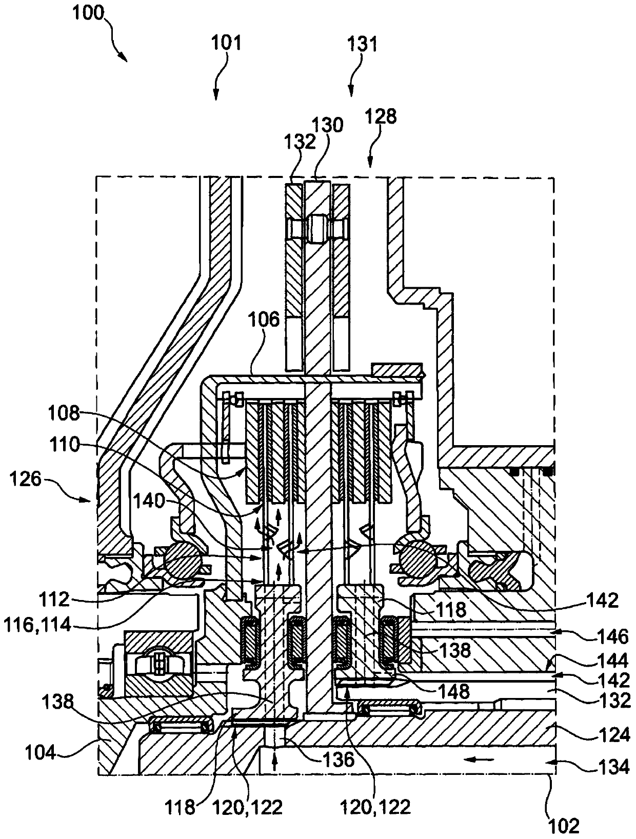
[0023] figure 1 A clutch 100 is shown in half section. The clutch 100 has an axis of rotation 102 , wherein only the elements arranged above the axis of rotation 102 are shown. The illustrated clutch 100 is a double clutch comprising two separate clutches 101 and 131 , which are arranged axially relative to one another here by way of example. In other embodiments, however, the invention can also be provided on a double clutch or a single clutch with a radial configuration.

[0024] A drive shaft 104 is provided for connection with a drive motor. The drive motor may be, for example, part of a drive train in a motor vehicle. The drive shaft 104 is rotationally coupled to a clutch housing 106 , which extends cup-shaped and symmetrical in the axial direction with respect to the axis of rotation 102 . The clutch housing 106 has radial projections or grooves on its radially inwardly directed surface for a form-fitting engagement with the friction elements 108 . The friction ele...


PUM


Abstract

The invention relates to a sintered clutch hub comprising radially inner teeth for cooperating with shaft teeth, radially outer teeth for cooperating with friction elements and for passing fluid in the direction of the friction elements radial channel. The invention also relates to a method for manufacturing a clutch hub, comprising the steps of: filling powder into a mold, on which a first toothing is formed radially on the inside and a second tooth is formed on the radially outside teeth; pressing the powder in the mold into a green body, the green body having inner teeth for cooperating with the shaft and outer teeth for cooperating with the friction element; arranging the radial direction in the green body channel; and heating the green body to compact it.

Description

technical field [0001] The invention relates to a clutch. The invention relates in particular to clutches in the drive train of a motor vehicle. Background technique [0002] A clutch for a drive train comprises a first and a second friction partner, which are mounted rotatably relative to a common axis of rotation and are axially pressed against one another for force transmission between them. The first friction element may comprise a plurality of lamellas and the second friction element may comprise a plurality of friction linings, wherein the lamellas and the friction linings are arranged alternately in an axial stack. The laminae include internal toothing that cooperates with the toothing of the clutch hub. Instead, the friction linings have external toothing, which fit into corresponding openings in the clutch housing. These toothings allow the friction partners to transmit forces in the circumferential direction while maintaining axial movement. The mutual pressing...

Claims


Application Information

Patent Timeline
Patent Type & Authority Patents(China)
IPC IPC(8): F16D13/74F16D13/58B22F3/03B22F5/08
CPCF16D25/123F16D2021/0607F16D2021/0615F16D2021/0692F16D25/082F16D25/10
Inventor E·洛伦茨
Owner SCHAEFFLER TECH AG & CO KG
Why Eureka
Try Eureka