Novel induction cooker

An induction cooker and a new type of technology, applied in the field of induction cookers, can solve the problems of easy failure, burnt coil disk and circuit board components, unreasonable cooling air duct planning, etc. ideal effect

Active Publication Date: 2014-06-25
佛山市顺德区普发特电器实业有限公司
View PDF6 Cites 10 Cited by
  • Summary
  • Abstract
  • Description
  • Claims
  • Application Information

AI Technical Summary

Problems solved by technology

[0002] The existing induction cooker has the following defects: 1), the layout design of the cooling fan, the main board, and the coil plate is not reasonable enough, and the planning of the cooling air duct is not reasonable enough, so that the temperature of the main board, the coil plate, etc. is high during work, and failures are prone to occur; 2), The air inlet of the heat dissipation fan is set at the bottom of the shell, and the bottom oil fume, dust, moisture, etc. are easily brought into the shell directly by the fan, which will damage the fan, affect the heat dissipation effect, or cause the circuit board or coil plate to burn out; 3), the bottom is set The structure of the fan is easy to suck newspapers, rags and other objects on the countertop, block the air inlet, and cause the induction cooker to lose its heat dissipation function, resulting in faster temperature rise in the inner cavity of the shell, burning out coil disks and circuit boards and other components; 4), the air outlet is only set The air is blown from one side, so that the heat is easily squeezed in the shell, and the residence time is too long, so that the high temperature inside the shell is maintained for a long time, which affects the operation of the main board

Method used


Image

  • Novel induction cooker
  • Novel induction cooker
  • Novel induction cooker

Examples


Embodiment Construction

[0032] The present invention will be further described below in conjunction with the accompanying drawings and embodiments.

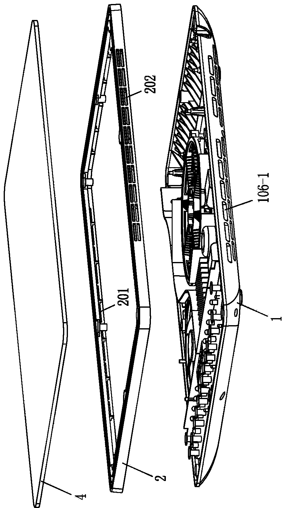
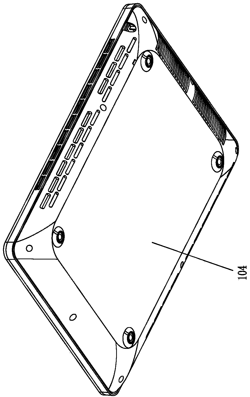
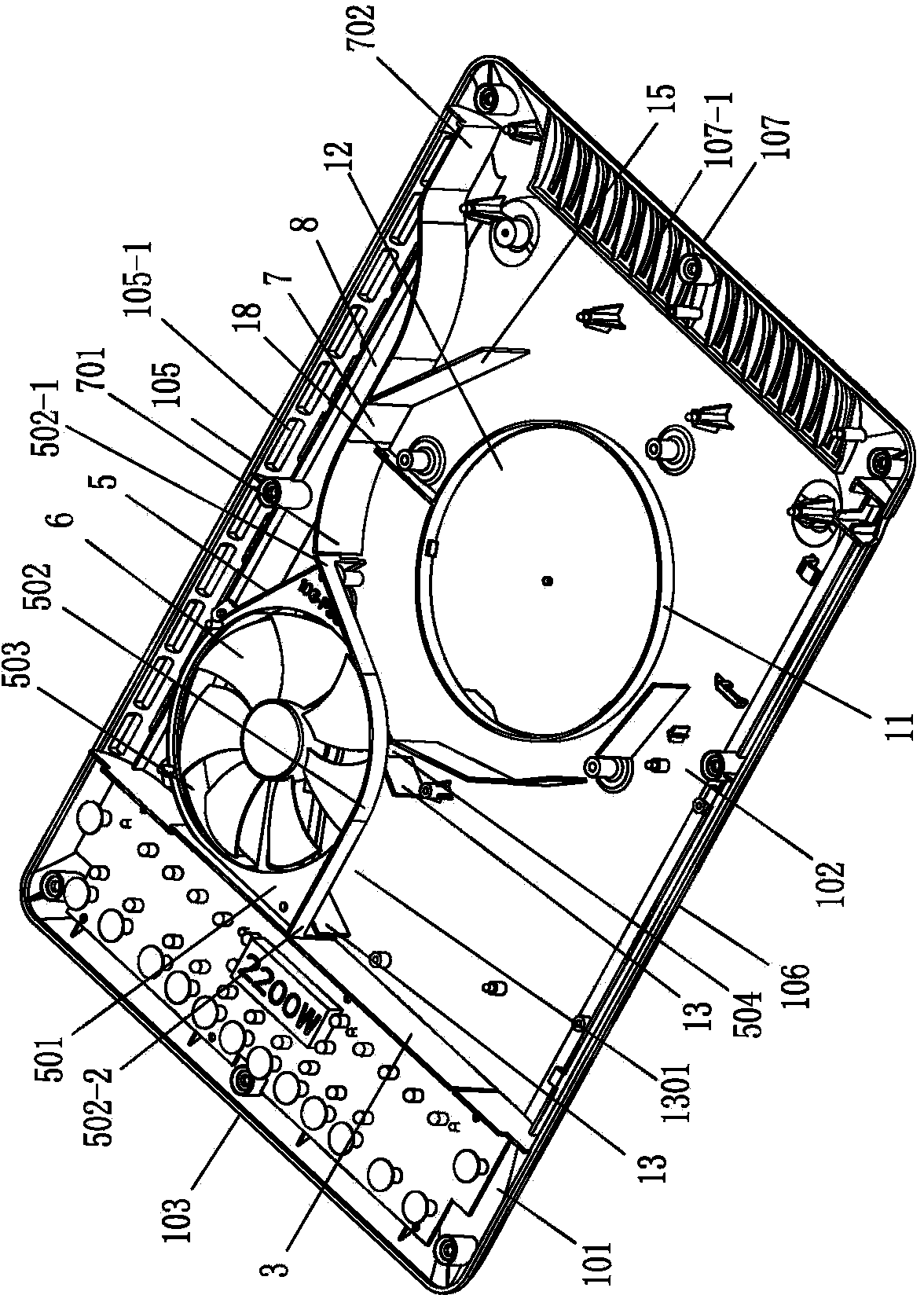
[0033] Such as Figure 1 to Figure 6 As shown, a new type of induction cooker includes a bottom shell 1 and a surface shell 2. The inner cavity of the bottom shell 1 is divided into a control panel area 101 and a component installation area 102 by a functional partition plate 3. The control panel area 101 is arranged on the bottom shell 1. The front side 103 and the bottom surface 104 of the bottom case 1 are airtight, forming a hidden heat dissipation fan structure. The face case 2 is covered on the bottom case 1, and the face case 2 is connected with a microcrystalline plate 4. It is characterized in that the element The two sides of the bottom case 1 corresponding to the installation area 102 respectively form an air intake side 105 and an exhaust side 106, and the air intake side 105 and the exhaust side 106 are correspondingly provided with a plura...


PUM


Abstract

The invention relates to a novel induction cooker. The novel induction cooker is characterized in that an inner cavity of a bottom shell is divided into a control panel region and an element mounting region by a functional partition board, wherein the control panel region is arranged on the front side of the bottom shell, the bottom surface of the bottom shell is closed, a face shell is arranged on the bottom shell and is connected with a microcrystalline board, an air inlet side face and an air outlet side face are respectively formed by two side faces, corresponding to the element mounting region, of the bottom shell, a plurality of air inlets and a plurality of first exhausting holes convective with one another are correspondingly formed in the air inlet side face and the air outlet side face, and a plurality of second exhausting holes are formed in the rear side face, corresponding to the element mounting region, of the bottom shell; a cooling fan is fixed at an opposite-angle position formed by the functional partition board and the air inlet side face through an air collection box, an air inlet guiding baffle is fixed in the element mounting region adjacent to the inner sides of the air inlets, a circuit main board is fixed at the element mounting region between an air outlet of the air collection box and the first exhausting holes, and a coil panel is fixed at the element mounting region between the air outlet of the air collection box and the second exhausting holes. The novel induction cooker has the beneficial effects that the structure is simple and reasonable, an air inlet area and an air outlet are increased, and the cooling speed is high.

Description

technical field [0001] The invention relates to the technical field of an electromagnetic cooker, in particular to an electromagnetic cooker with reasonable layout and good heat dissipation effect. Background technique [0002] The existing induction cooker has the following defects: 1), the layout design of the cooling fan, the main board, and the coil plate is not reasonable enough, and the planning of the cooling air duct is not reasonable enough, so that the temperature of the main board, the coil plate, etc. is high during work, and failures are prone to occur; 2), The air inlet of the heat dissipation fan is set at the bottom of the shell, and the bottom oil fume, dust, moisture, etc. are easily brought into the shell directly by the fan, which will damage the fan, affect the heat dissipation effect, or cause the circuit board or coil plate to burn out; 3), the bottom is set The structure of the fan is easy to suck newspapers, rags and other objects on the countertop, ...

Claims


Application Information

Patent Timeline
Patent Type & Authority Applications(China)
IPC IPC(8): F24C7/00F24C15/00H05K7/20
Inventor 黎结芝
Owner 佛山市顺德区普发特电器实业有限公司
Why Eureka
Try Eureka