Communication method for multiple electronic detonators with shared leg wire
A technology of electronic detonators and communication methods, applied in fuzes, weapon accessories, offensive equipment, etc., can solve problems such as the inability to realize simple communication between a host computer and multiple electronic detonators that share a common leg, achieve easy training and construction, and reduce rejection Explosion rate, the effect of reducing the use of footlines
- Summary
- Abstract
- Description
- Claims
- Application Information
AI Technical Summary
Problems solved by technology
Method used
Image
Examples
Embodiment 1
[0075] In this embodiment, the type code of the electronic detonator is injected into the electronic detonator during the production stage, and the feature information is the extension of the electronic detonator as an example for illustration.
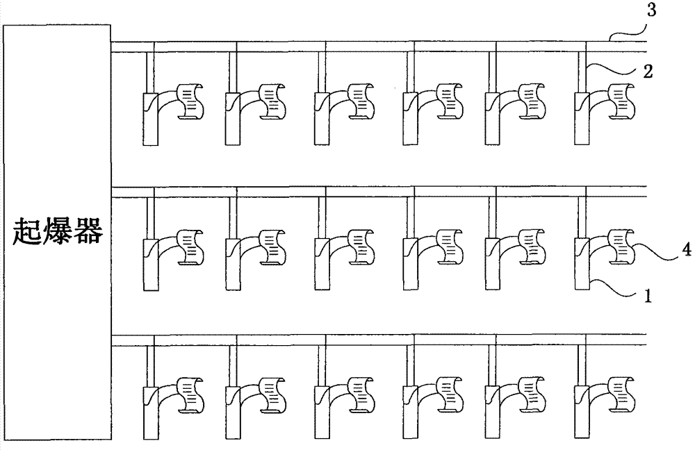
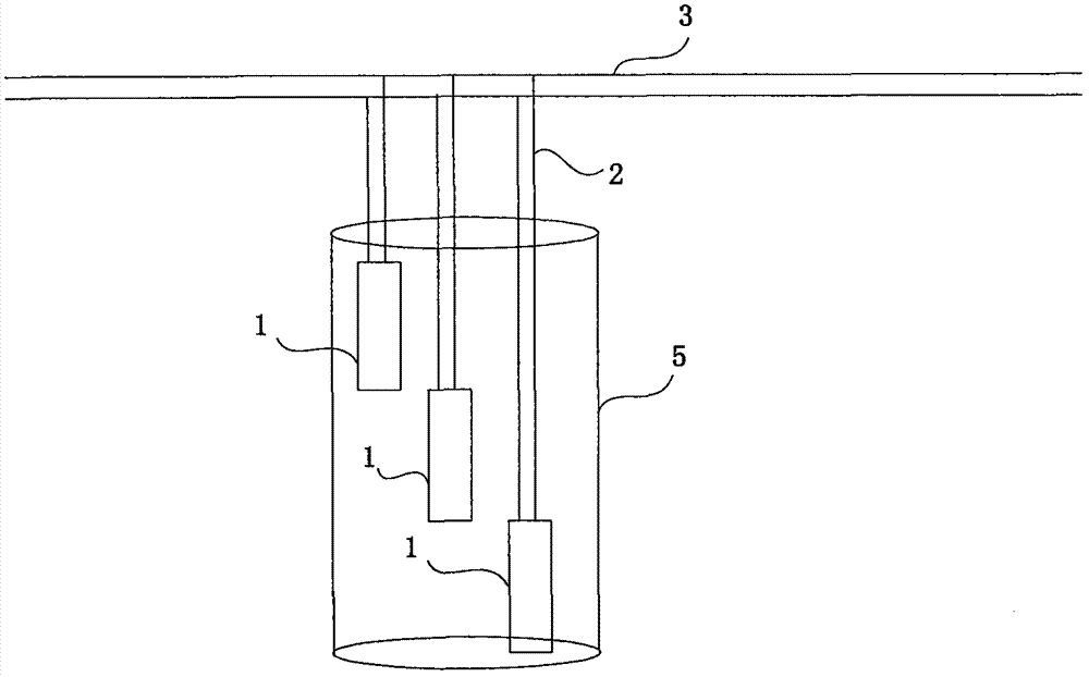
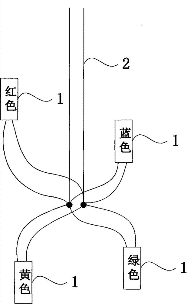
[0076] Step 101: Connect multiple electronic detonators with different types of codes in parallel to the same leg line. This step includes the following sub-steps:
[0077] Sub-step A1: Set the type code.
[0078] Assuming that the number of electronic detonators sharing the leg is 4, then set 4 type codes, which are 0, 1, 2 and 3 respectively.
[0079] Sub-step A2: Injecting the type code into the electronic detonator.
[0080] During the production process of each electronic detonator, a type code is randomly written into the memory of each electronic detonator control circuit.
[0081] Sub-step A3: Coat the body of the electronic detonator injected with the same type code with the same color.
[0082] In this example, paint the ...
Embodiment 2
[0102]In this embodiment, the type code of the electronic detonator is injected into the electronic detonator during the production stage, and the feature information is the network address of the electronic detonator as an example for illustration.
[0103] Step 201: Connect multiple electronic detonators with different types of codes in parallel to the same leg. The specific process of this step is exactly the same as sub-step A1-sub-step A4.
[0104] Step 202: Connect the foot wire with the electronic detonator signature reader.
[0105] Step 203: The electronic detonator characteristic reader / writer sends the type code and characteristic information to the four electronic detonators sharing the footline respectively according to the position of the footline in the detonation network.
[0106] In this example, the characteristic information is the network address of the electronic detonator, and the network address of the electronic detonator is set as the initiation branch...
Embodiment 3
[0124] In this embodiment, the type code of the electronic detonator is injected into the electronic detonator during the production stage, and the characteristic information is the number of the blasting hole and the serial number in the hole as an example.
[0125] Step 301: Connect multiple electronic detonators preset with different types of codes in parallel to the same leg. The specific process of this step is the same as sub-steps A1-A4.
[0126] Step 302: Connect the foot wire with the electronic detonator signature reader.
[0127] Step 303: The electronic detonator characteristic reader / writer sends the type code and characteristic information to the four electronic detonators sharing the footline respectively according to the position of the footline in the detonation network.
[0128] In this example, the feature information is the blasthole number and the hole sequence number. Assuming that the four electronic detonators connected to the foot wire are buried in t...
PUM
 Abstract
Description
Claims
Application Information
 - R&D
- Intellectual Property
- Life Sciences
- Materials
- Tech Scout
- Unparalleled Data Quality
- Higher Quality Content
- 60% Fewer Hallucinations
Browse by: Latest US Patents, China's latest patents, Technical Efficacy Thesaurus, Application Domain, Technology Topic, Popular Technical Reports.
© 2025 PatSnap. All rights reserved.Legal|Privacy policy|Modern Slavery Act Transparency Statement|Sitemap|About US| Contact US: help@patsnap.com


