Temperature rise test method for large transformer

A temperature rise test and transformer technology, applied in instruments, measuring electrical variables, components of electrical measuring instruments, etc., can solve the problems of high rated voltage, low load factor, low impedance voltage, etc., to achieve high accuracy, Reasonable structure and easy operation effect

Active Publication Date: 2014-06-25
SHANDONG DACHI ELECTRIC
View PDF4 Cites 10 Cited by
  • Summary
  • Abstract
  • Description
  • Claims
  • Application Information

AI Technical Summary

Problems solved by technology

However, due to the low impedance voltage drop of the tested product and the high rated voltage of a single compensation capacitor, the capacity of the capacitor cannot be fully conveyed, that is, the load factor cannot be increased; at the same time, there are still small current transformer ratios and current carrying capacity of the test

Method used


Image

  • Temperature rise test method for large transformer

Examples


Embodiment Construction

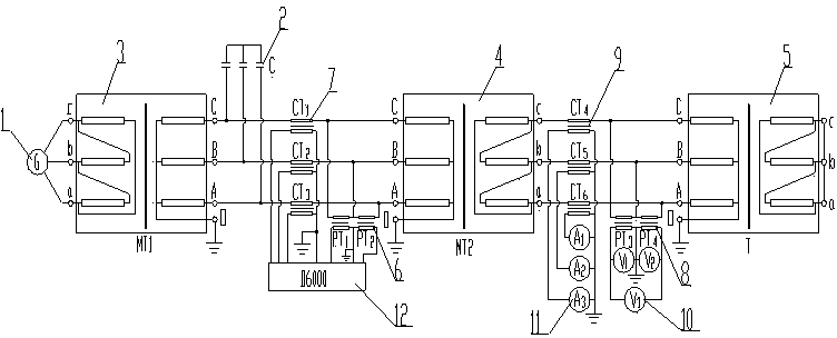
[0020] The drawings show specific embodiments of the invention. Such as figure 1 As shown, the test circuit of this large transformer temperature rise test method is connected as follows:

[0021] ⑴Firstly, connect the output terminal of the power frequency generator set 1 to the reactive power compensation capacitor 2 through the intermediate transformer 3; select the standard voltage transformer 6 for power analyzer and the standard current transformer for power analyzer based on the output voltage and current of the power supply The tap position of the power analyzer 7 is connected in series with the tap position of the standard current transformer 7 to the output terminals of the intermediate transformer 3 and the reactive power compensation capacitor 2, and then through the bus bar, isolation switch, cable and temporary intermediate transformer The high-voltage side of 4 is connected, and the tap position of the standard voltage transformer 6 for the power analyzer is c...


PUM


Abstract

The invention relates to the field of transformer temperature rise tests, in particular to a temperature rise test method for a for large transformer. According to the temperature rise test method for the large transformer, a temperature rise test is conducted on a product to be tested by connecting a power-frequency power generation set, a reactive compensation capacitor, an intermediate transformer, a temporary intermediate transformer, a standard-voltage transformer for a power analyzer, a standard-current transformer for the power analyzer, a standard-voltage transformer for monitoring, a sleeve type current transformer for monitoring, an effective voltmeter for monitoring, an ampere meter for monitoring and the power analyzer to the product to be tested after the power-frequency power generation set, the reactive compensation capacitor, the intermediate transformer, the temporary intermediate transformer, the standard-voltage transformer for the power analyzer, the standard-current transformer for the power analyzer, the standard-voltage transformer for monitoring, the sleeve type current transformer for monitoring, the effective voltmeter for monitoring, the ampere meter for monitoring and the power analyzer are connected according to a certain sequence, or directly connecting the power-frequency power generation set, the reactive compensation capacitor, the intermediate transformer, the temporary intermediate transformer, the standard-voltage transformer for the power analyzer, the standard-current transformer for the power analyzer, the standard-voltage transformer for monitoring, the sleeve type current transformer for monitoring, the effective voltmeter for monitoring, the ampere meter for monitoring and the power analyzer to the product to be tested. According to the temperature rise test method for the large transformer, the structure of a test circuit is simple, operation is easy, the accuracy degree is high, and the method is suitable for the test items such as load tests or temperature rise tests of low-voltage and large-capacity power transformers with voltages equal to or higher than 20kV-35kV and capacities equal to or higher than 50000 KVA, and low-voltage and large-capacity special transformers.

Description

(1) Technical field [0001] The invention relates to the field of transformer temperature rise test, in particular to a large transformer temperature rise test method. (2) Background technology [0002] With the development of economy, some power users' demand for the capacity of a single transformer has exceeded the scope specified in GB / T6451-2008, especially some foreign users, whose product capacity is sometimes the same (or adjacent) voltage recommended by the national standard Several times the maximum capacity of the grade; according to the conventional test plan, when the temperature rise test under the total loss condition is carried out on it, a considerable part of the existing test equipment of the transformer manufacturer in China cannot meet the requirements. The value of the temperature rise of the transformer is directly related to the service life and operational reliability of the transformer. For these reasons, the temperature rise test is also listed as...

Claims


Application Information

Patent Timeline
IPC IPC(8): G01R31/00G01R1/28
Inventor 董景义祝文正吕燚
Owner SHANDONG DACHI ELECTRIC
Why Eureka
Try Eureka