Laser control circuit and method and laser level provided with control circuit

A technology for controlling circuits and lasers, applied in the field of laser ink line instruments, can solve problems such as damage to the laser tube, large peak interference amplitude, and monotonous function.

Active Publication Date: 2014-06-25
CHANGZHOU HUADA KEJIE OPTO ELECTRO INSTR
View PDF5 Cites 4 Cited by
  • Summary
  • Abstract
  • Description
  • Claims
  • Application Information

AI Technical Summary

Problems solved by technology

[0003] Since the control circuit in the above method sends the same control signal to all laser tubes at the same time, all laser tubes are turned on or off in the same state, and the function is relatively monotonous, which cannot meet the needs of users.
Moreover, more importantly, the simultaneous on / off of the laser tube will cause spike interference on the power supply. When the current is large, the amplitude of the spike interference is also large, which will greatly damage the laser tube.

Method used


Image

  • Laser control circuit and method and laser level provided with control circuit
  • Laser control circuit and method and laser level provided with control circuit
  • Laser control circuit and method and laser level provided with control circuit

Examples


Embodiment Construction

[0019] The advantages of the present invention are further described below with reference to the accompanying drawings and specific embodiments.

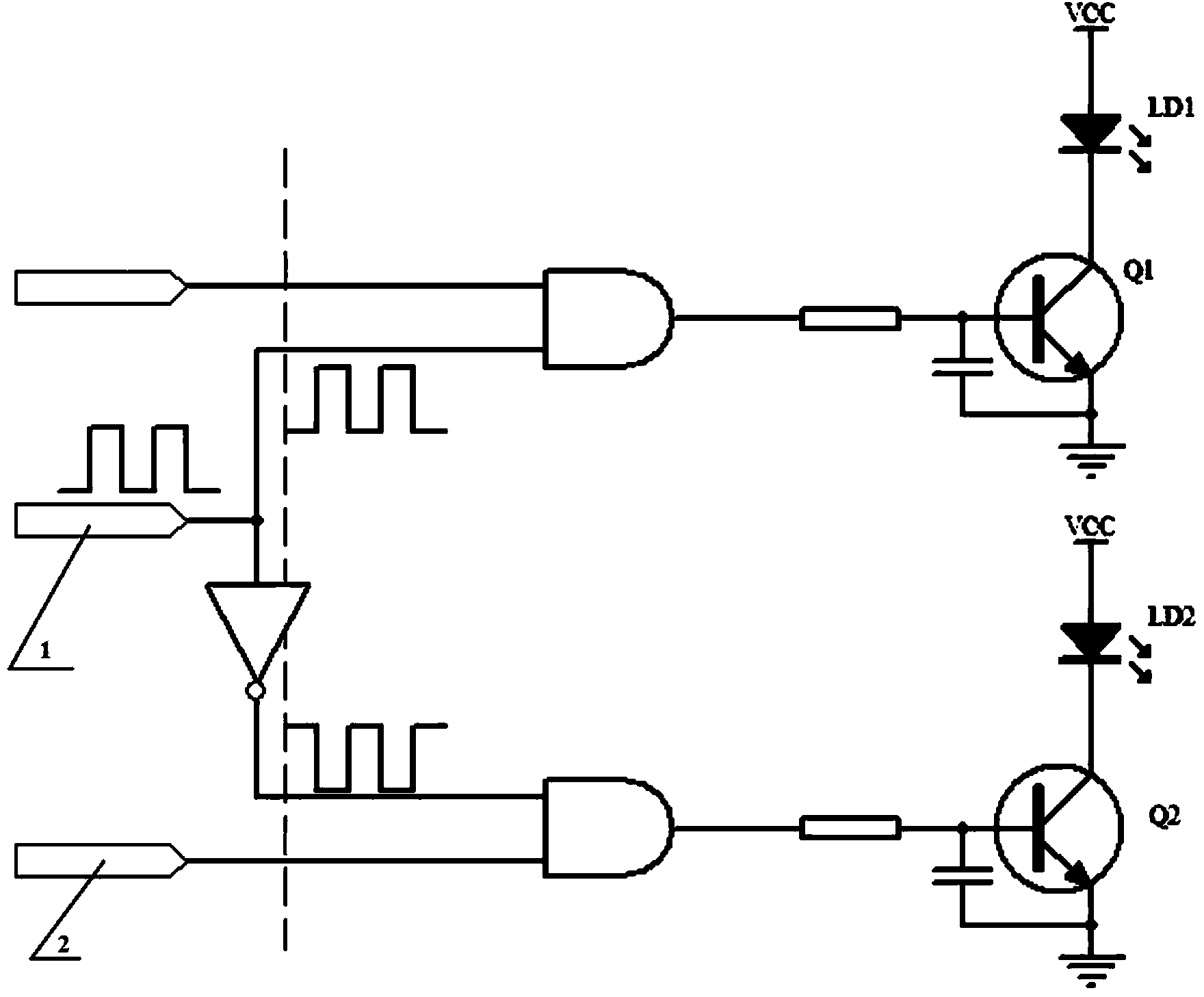
[0020] like figure 2 As shown, it is a schematic diagram of the configuration of the control circuit in a preferred embodiment of the present invention. The laser control circuit includes at least two laser tubes and a control unit for controlling the at least two laser tubes respectively, and the control unit sends a control signal to each laser tube to control the on / off state of the laser tube. In the present invention, in order to solve the above problem, at least two laser tubes are firstly divided into two groups, namely the first laser tube group and the second laser tube group. The grouping method is not limited, and the user can work according to the actual work. It is required to classify the lasers that need to display different states into the first group or the second group. For example, one laser tube is defined as t...


PUM


Abstract

The invention discloses a laser control circuit. The laser control circuit comprises at least two laser tubes and a control unit respectively controlling the at least two laser tubes. The control unit transmits control signals to the at least two laser tubes to control the at least two laser tubes to be turned on / off; the control unit comprises a main pulse signal generator and a logic control unit; the main pulse signal generator, the logic control unit and the at least two laser tubes are sequentially connected, the logic control unit divides the control signals into control signals different in type and transmits the signals to the at least two laser tubes, so that the at least two laser tubes are in different working states. By the adoption of the technical scheme, the laser tubes can be controlled more flexibly, working currents of the laser tubes are reduced and are more stable and continuous, and therefore the phenomenon of peak interference is avoided.

Description

technical field [0001] The invention relates to the field of laser equipment, in particular to a laser control laser control circuit, a control method and a laser ink line meter with the control circuit. Background technique [0002] The laser ink line instrument has been a conventional configuration in the field of laser equipment. For the control of the laser tube of the laser ink line instrument, the following methods are generally used: figure 1 As shown, a very simple control circuit is designed, each laser tube is equipped with a control signal generator, and the on-off of the laser tube is controlled by directly sending square waves or high and low levels. [0003] Since the control circuit in the above method sends the same control signal to all the laser tubes at the same time, the on or off states of all the laser tubes are the same, and the function is relatively monotonous, which cannot meet the needs of users. Moreover, more importantly, turning on / off the las...

Claims


Application Information

Patent Timeline
Patent Type & Authority Applications(China)
IPC IPC(8): H01S5/042G01C15/00
CPCH01S5/06216H01S5/4025H01S5/0428H01S5/0427
Inventor 张瓯牛青傅俊杰
Owner CHANGZHOU HUADA KEJIE OPTO ELECTRO INSTR
Why Eureka
Try Eureka