
Induction machine rotor field directional deviation correction method based on torque estimation

A technology of rotor magnetic field orientation and magnetic field orientation, which is used in the control of generators, motor generators, electronic commutation motor control, etc. The effect of torque output capability, improving dynamic response capability, and enhancing system performance

Active Publication Date: 2014-06-25
HUAZHONG UNIV OF SCI & TECH
View PDF6 Cites 5 Cited by
  • Summary
  • Abstract
  • Description
  • Claims
  • Application Information

AI Technical Summary

Problems solved by technology

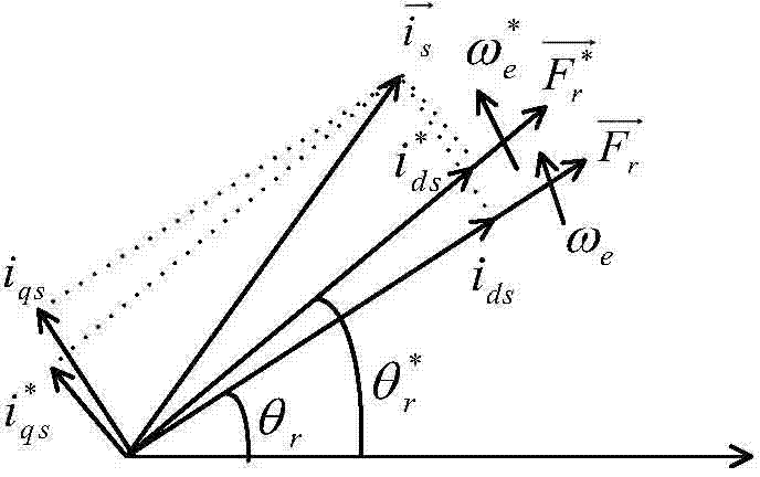
The calculation of the rotor field orientation angle in the actual system involves some parameters of the motor and the d-axis and q-axis command currents in the rotating coordinate system, so the inaccurate parameters used in the calculation process will cause a large deviation in the field orientation angle, especially When the motor works in the field-weakening high-speed area, due to the change of the magnetic field caused by temperature rise and field weakening, the motor parameters will change more obviously. If real-time and accurate parameter updates cannot be performed, the error change of the magnetic field orientation will be further aggravated. At the same time, Due to the inaccurate field orientation and the decline of current control performance in the field weakening area, the d-axis and q-axis current command values ​​are different from the actual values, which will also lead to deviations in field orientation

Method used


Image

  • Induction machine rotor field directional deviation correction method based on torque estimation
  • Induction machine rotor field directional deviation correction method based on torque estimation
  • Induction machine rotor field directional deviation correction method based on torque estimation

Examples


Embodiment Construction

[0018] In order to make the object, technical solution and advantages of the present invention more clear, the present invention will be further described in detail below in conjunction with the accompanying drawings and embodiments. It should be understood that the specific embodiments described here are only used to explain the present invention, not to limit the present invention. In addition, the technical features involved in the various embodiments of the present invention described below can be combined with each other as long as they do not constitute a conflict with each other.

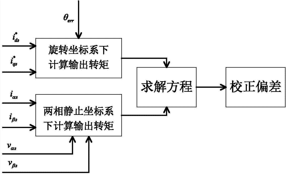
[0019] see figure 1 , the correction method of the present invention specifically comprises the following steps:

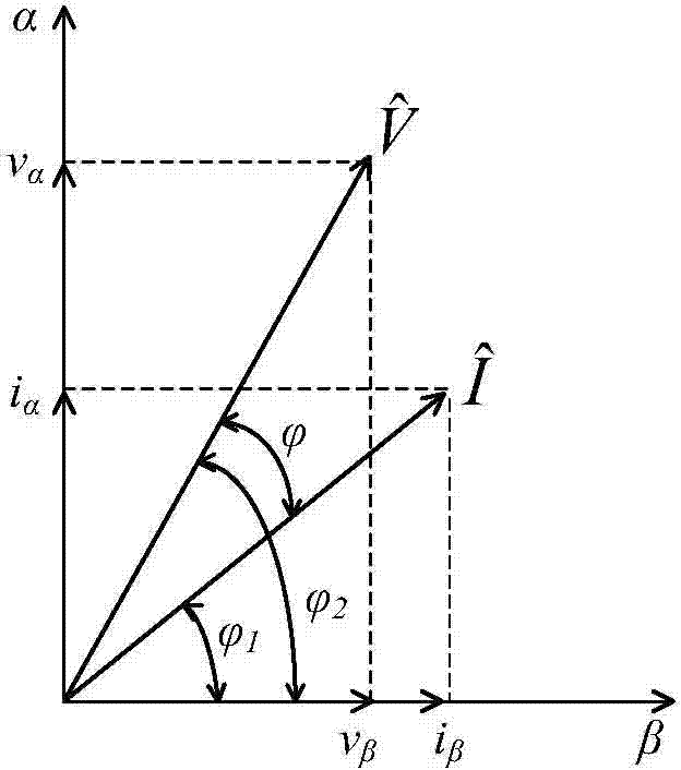
[0020] 1. Use the voltage and current in the two-phase stationary coordinate system to calculate the output torque.

[0021] The output mechanical power of the induction motor is P mech =(1-s)P gap , where P mech is the mechanical power, s is the slip rate, P gap is the air...


PUM


Abstract

The invention provides an induction machine rotor field orientation deviation correction method based on torque estimation. Two methods are respectively adopted in the induction machine rotor field orientation deviation correction method to calculate the output torque of an induction machine. First, voltage and current under a two-phase static coordinate in a vector control system is utilized to calculate output power of the induction machine, and the output torque of the sensing motor is obtained through estimation. Second, by means of current instruction values of a d shaft and a q shaft under a rotating coordinate of the vector control system and a magnetic field orientation deviation angle, the output torque of the sensing motor is obtained through calculation, then an equation of torque composition comprising the magnetic field orientation deviation angle is obtained through calculation of the two methods, the magnetic field orientation deviation angle is solved through the equation, and deviation correction is achieved. The induction machine rotor field orientation deviation correction method based on torque estimation improves accuracy of magnetic field orientation in a traditional sensing motor vector control method, particularly the orientation precision of speed operation of a weak magnetic region.

Description

technical field [0001] The invention belongs to the technical field of AC induction motor control, and in particular relates to a method for correcting the magnetic field orientation deviation angle of an induction motor vector control system. Background technique [0002] AC motor frequency conversion speed regulation methods mainly include open-loop V / f speed regulation and closed-loop speed regulation. Closed-loop speed regulation is also called vector control method, which specifically includes indirect rotor field orientation, direct rotor field orientation, and direct stator field orientation. Among them, the indirect rotor field orientation is widely used because it needs less hardware and has high control performance. [0003] The principle of indirect rotor field-oriented vector control of induction motors is as follows: the rotating coordinate system is established on the direction of the rotor magnetic field, and through this coordinate, the stator current is deco...

Claims


Application Information

Patent Timeline
Patent Type & Authority Applications(China)
IPC IPC(8): H02P21/08
Inventor 刘洋
Owner HUAZHONG UNIV OF SCI & TECH
Learn More