Shielding Composite Membrane

A composite diaphragm and magnetic conduction technology, applied in the direction of magnetic/electric field shielding, electrical components, etc., can solve the problems of easy delamination and falling off, no insulation layer, etc., to improve the isolation and shielding performance, increase the effective area and depth, and improve the structure The effect of stability

Active Publication Date: 2014-06-25
IND TECH RES INST
View PDF6 Cites 15 Cited by
  • Summary
  • Abstract
  • Description
  • Claims
  • Application Information

AI Technical Summary

Problems solved by technology

At present, the commonly used electromagnetic interference (EMI) shielding diaphragm is mainly based on electric field shielding. Its insulating layer does not have any other functions, and it is easy to delaminate and fall off when electrically pressed.

Method used


Image

  • Shielding Composite Membrane
  • Shielding Composite Membrane
  • Shielding Composite Membrane

Examples


Embodiment Construction

[0028] The detailed features and advantages of the present invention are described in detail below in the embodiments, the content of which is sufficient for any person familiar with the related art to understand the technical content of the present invention and implement it accordingly, and according to the content of the present invention, claims and accompanying drawings, The related objects and advantages of the present invention can be easily understood by anyone skilled in the related art. The following examples further illustrate the concept of the present invention in detail, but do not limit the scope of the present invention in any way.

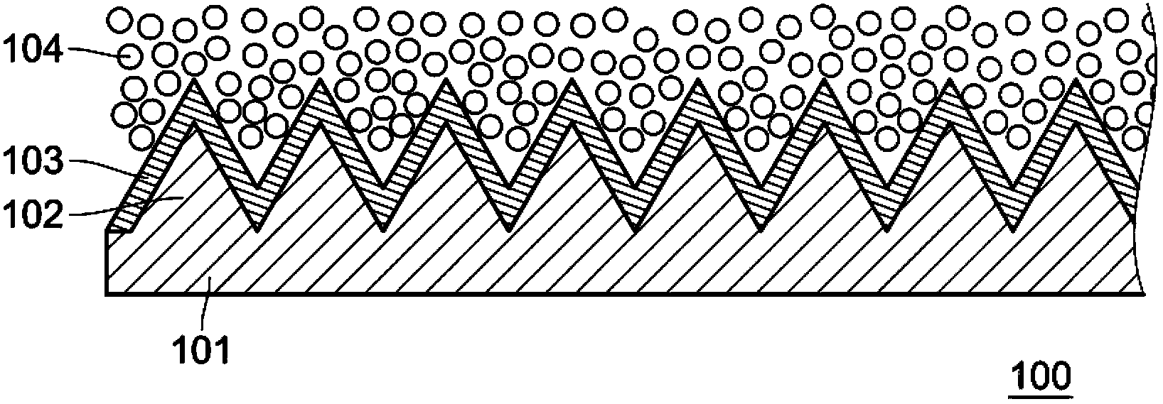
[0029] Please refer to figure 1 , is a schematic diagram of a shielding composite diaphragm 100 disclosed in the present invention. This embodiment is a shielding composite membrane 100 , and the shielding composite membrane 100 includes a magnetically conductive layer 101 , a plurality of magnetically conductive bumps 102 , a con...


PUM


Abstract

The present invention discloses a shielding composite membrane including a magnetic conductive layer, multiple magnetic conductive convex blocks, a conductor layer and a conductive rubber layer. The multiple magnetic conductive convex blocks are installed on the magnetic conductive layer. The conductor layer is installed on the magnetic conductive convex blocks and is between the magnetic conductive convex blocks and the conductive rubber layer, multiple holes which are connected with each other are formed between the magnetic conductive layer, the conductive rubber layer and the bottoms of the magnetic conductive convex blocks.

Description

technical field [0001] The invention relates to a membrane, in particular to a shielding composite membrane. Background technique [0002] The operation of electronic devices (such as televisions, radios, computers, medical instruments, business machines, communication equipment, and the like) is accompanied by the generation of electromagnetic radiation from the electronic circuits of the electronic devices, which may radiate to other components in the electronic device components and interfere with them. This radiation typically develops as transients in the radio frequency band of the electromagnetic spectrum (ie, between about 10 KHz and 10 GHz), and is referred to as electromagnetic interference (EMI). [0003] In normal operation, electronic devices will generate electromagnetic energy released by radiation and conduction, which will affect the transmission of adjacent electronic devices. This electromagnetic interference (EMI) may cause attenuation or complete loss o...

Claims


Application Information

Patent Timeline
Patent Type & Authority Applications(China)
IPC IPC(8): H05K9/00
Inventor 唐敏注汤士源王丽君王燕萍
Owner IND TECH RES INST
Why Eureka
Try Eureka