

Electronic control apparatus
An electronic control device and control processing technology, applied in the direction of electrical digital data processing, instrumentation, error detection/correction, etc., can solve problems such as failure occurrence and inability to safely control machines
- Summary
- Abstract
- Description
- Claims
- Application Information
AI Technical Summary
Problems solved by technology
Method used
Image

Examples
Embodiment approach 1
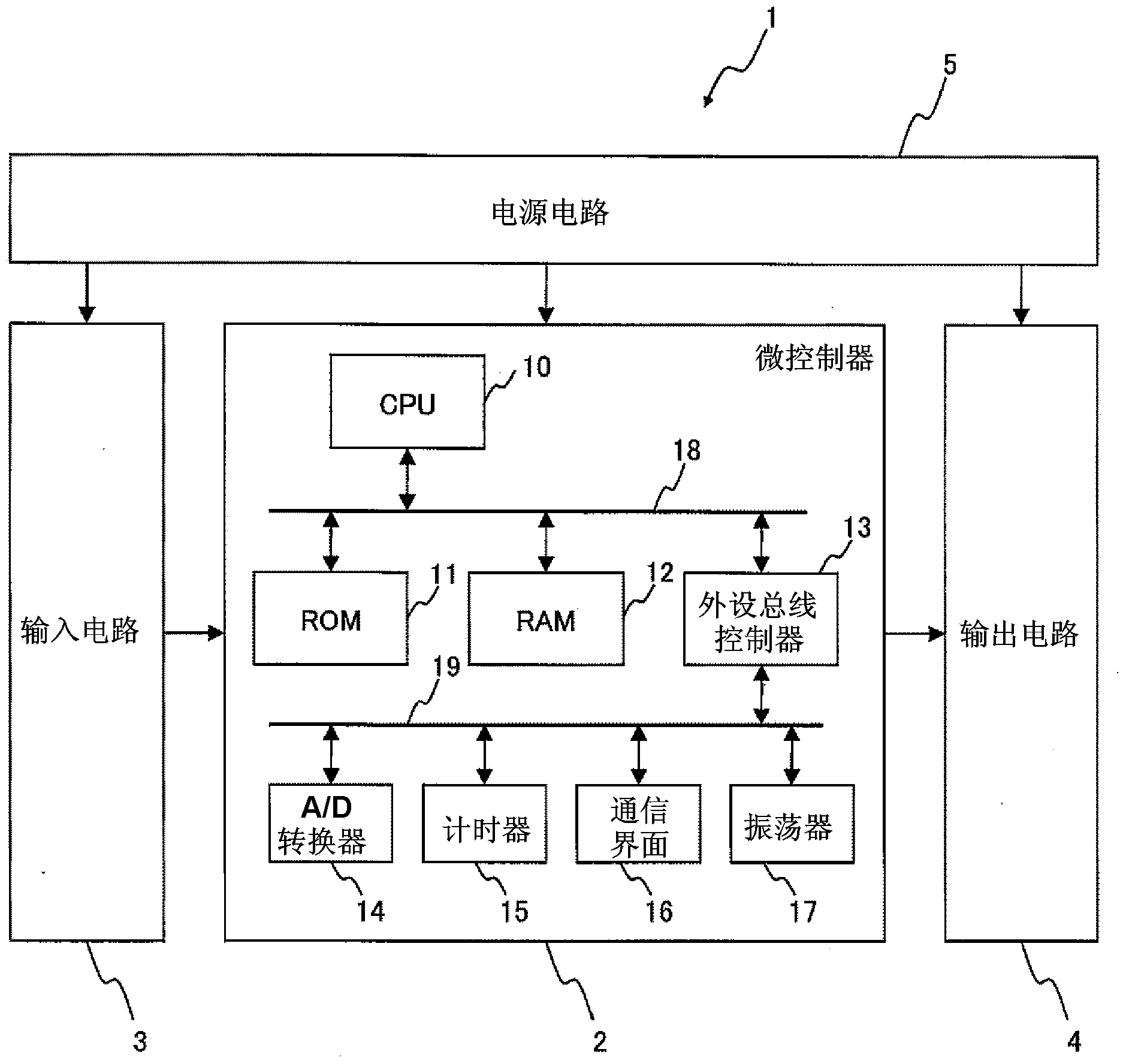
[0028] figure 1 It is a functional block diagram of the electronic control device 1 according to Embodiment 1 of the present invention. The electronic control device 1 is a device for electronically controlling equipment, and includes a microcontroller 2 , an input circuit 3 , an output circuit 4 , and a power supply circuit 5 .
[0029] Microcontroller 2 has CPU (Central Processing Unit, central processing unit) 10, ROM (Read Only Memory, read-only memory) 11, RAM (Random Access Memory, random access memory) 12, peripheral bus controller 13, A / D converter 14 , timer 15 , communication interface (I / F) 16 , and oscillator 17 . The CPU 10 , ROM 11 , RAM 12 , and peripheral bus controller 13 are connected to an internal bus 18 . An A / D converter 14 , a timer 15 , a communication interface (I / F) 16 , an oscillator 17 , and a peripheral bus controller 13 are connected to a peripheral bus 19 .
[0030] The CPU 10 receives input signals from various sensors and other electronic c...
Embodiment approach 2
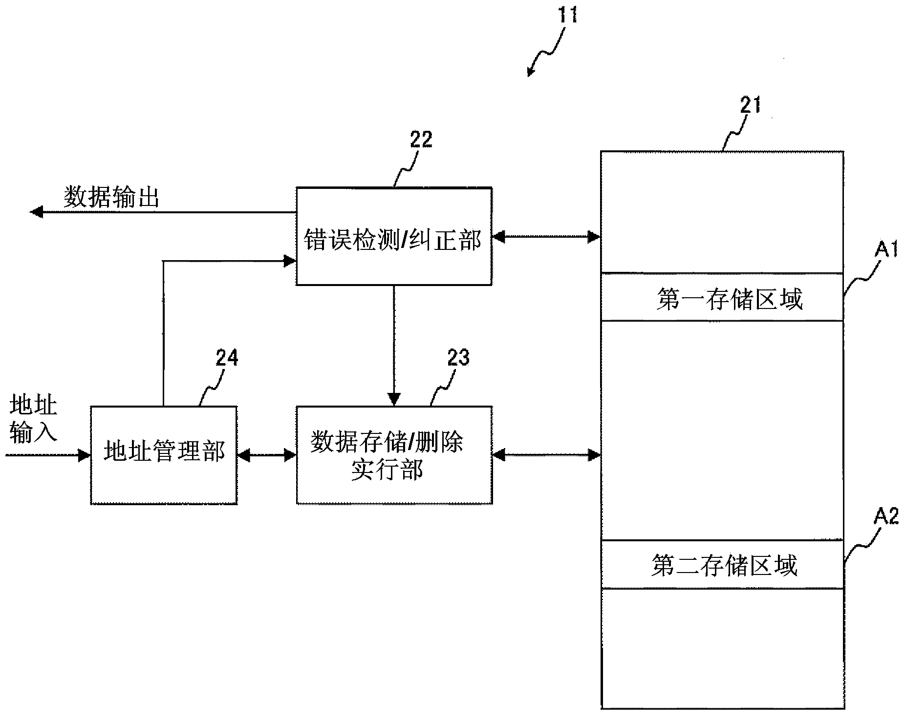
[0079] Figure 6 It is a figure which shows the structure of the program and data stored in the ROM11 with which the electronic control apparatus 1 of Embodiment 2 is equipped. The ROM 11 according to the second embodiment includes a data swap execution unit 25 instead of the data storage / deletion execution unit 23 described in the first embodiment. Other functional parts included in the electronic control device 1 are the same as those in the first embodiment. The same applies to RAM12.
[0080] When the data exchange execution unit 25 receives the notification of the detected data error from the error detection / correction unit 22, it exchanges the data stored in the first storage area A1 with the data stored in the second storage area A2. That is, in Embodiment 2, the second storage area A2 does not need to be a blank area. The specific processing flow will be described later. "Data storage" in the second embodiment is equivalent to the data exchange execution unit 25 . ...
Embodiment approach 3
[0104] Embodiment 3 of the present invention describes an operation example in which, when a data error is detected in the first storage area A1, the corrected data is not immediately stored in the second storage area A2, but the corrected data is stored when data errors accumulate to a certain extent. . Since the configuration of the electronic control device 1 is the same as that of the first embodiment, the following description will focus on differences.
[0105] Figure 9 It is a figure which shows the processing flow when the electronic control device 1 reads the data stored in the data storage part 21 in Embodiment 3. Below, for Figure 9 Each step is explained.
[0106] ( Figure 9 : Steps S10 to S12)
[0107] These steps are the same as those of Embodiment 1 Figure 4 Steps S10 to S12 are the same as described above. However, steps S15 to S16 are executed between steps S11 and S13, and step S17 is executed after step S12.
[0108] ( Figure 9 : step S15)
[...
PUM
 Abstract
Description
Claims
Application Information