Electric machine and method for assembling an electric machine

A connection method and drive shaft technology, applied in the direction of electromechanical devices, electrical components, mechanical equipment, etc., can solve the problems of damage to the drive shaft, the axial force cannot be arbitrarily increased, etc., and achieve the effect of reducing weight

Active Publication Date: 2014-06-25
SEG AUTOMOTIVE GERMANY GMBH
View PDF5 Cites 1 Cited by
  • Summary
  • Abstract
  • Description
  • Claims
  • Application Information

AI Technical Summary

Problems solved by technology

However, this axial force cannot be increased arbitrarily, since it is transmitted into the drive shaft and can lead to damage to the drive shaft during heavy use

Method used


Image

  • Electric machine and method for assembling an electric machine
  • Electric machine and method for assembling an electric machine

Examples


Embodiment Construction

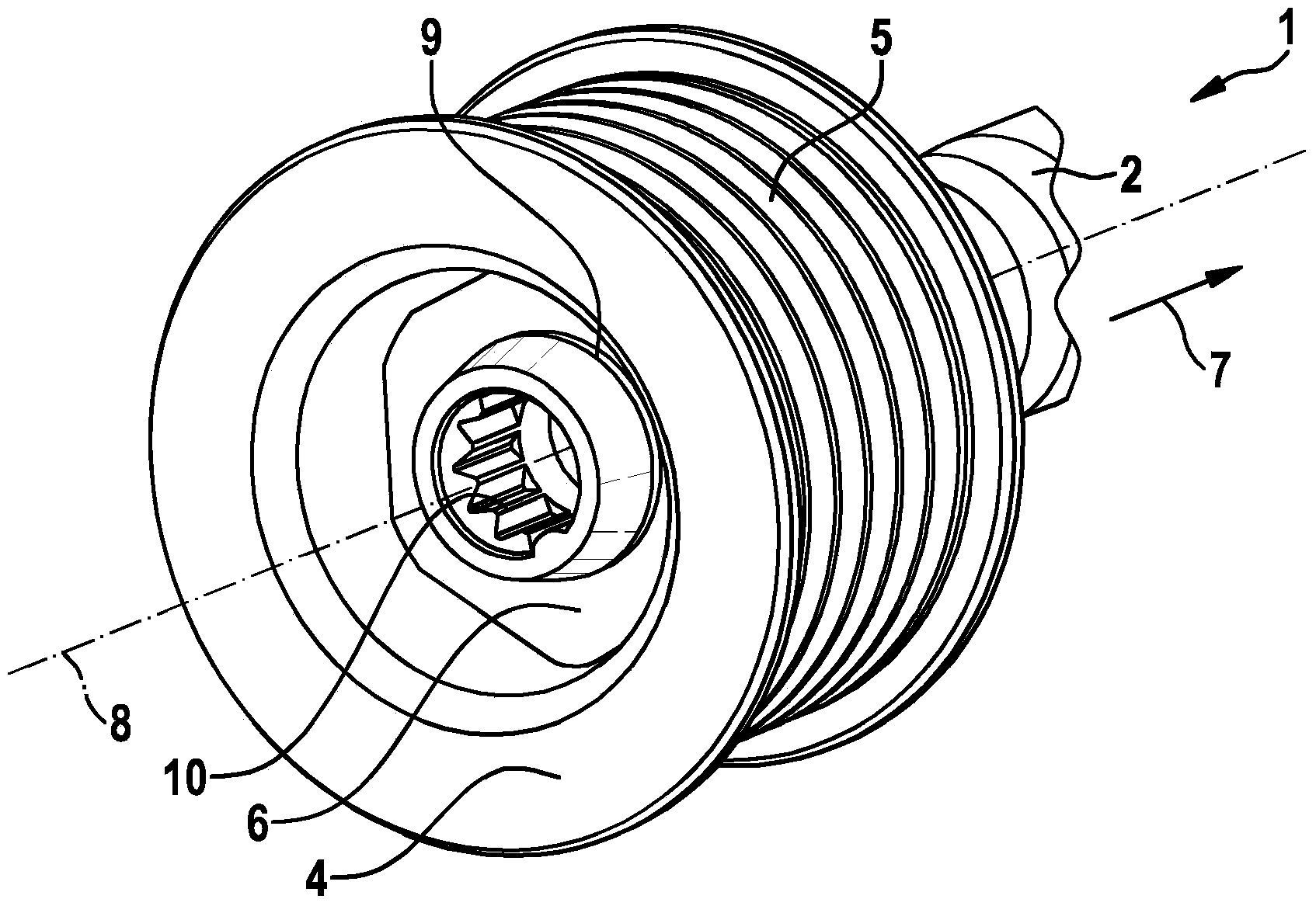
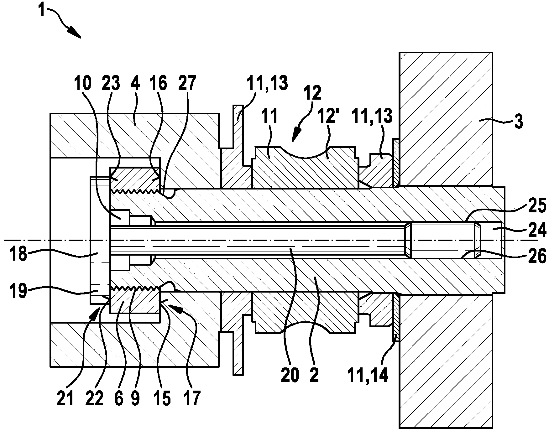
[0025] figure 1 A partial view of an electric machine 1 known from the prior art is shown. The electric machine 1 can be configured, for example, as an electric motor, generator or generator motor. It has a drive shaft 2 via which the electric motor can deliver or receive torque. A rotor 3 , not shown here, and a connecting element 4 , which is preferably axially spaced apart from the rotor 3 , are arranged on the drive shaft 2 . The connecting element 4 is configured, for example, as a belt pulley, ie has a running surface 5 for bending a loose encircling component, for example a running surface 5 for a belt. The connecting element 4 is fastened to the drive shaft 2 by means of a fastening element 6 and is pressed by the fastening element 6 in the direction of the rotor 3 , ie in the direction of the arrow 7 . The arrow 7 is here parallel to the longitudinal axis 8 of the drive shaft 2 and the electric motor 1 .

[0026] The fastening element 6 is designed as a nut, which...


PUM


Abstract

The invention relates to an electric machine (1), comprising a drive shaft (2), on which a rotor (3) and a connecting element (4) are arranged, at least partially force-closed torque transmission connection being formed between the rotor (3) and the connecting element (4) in that the connecting element (4) is pushed in the direction of the rotor (3) by means of a locking element (18). The locking element (18) is designed as a screw and has an external screw thread (25), which is screwed into an internal shaft thread (26) of the drive shaft (2). The invention further relates to a method for assembling an electric machine (1).

Description

technical field [0001] The invention relates to an electric machine having a drive shaft on which a rotor and a connecting element are arranged and in which the connecting element is pressed in the direction of the rotor by means of a locking element, whereby the rotor An at least partially force-transmitting torque-transmitting connection is formed with the connecting element. The invention also relates to a method for assembling an electric machine. Background technique [0002] Electric machines of the type mentioned at the outset are known in the prior art. Such an electrical machine can be designed as desired and is used in particular as an electric motor, generator or generator motor of a motor vehicle. The electric motor has a drive shaft, and the electric motor outputs or receives torque via the drive shaft. The rotor and the connecting element are arranged at least partially on the drive shaft. [0003] The rotor is mounted in the electric machine by means of a ...

Claims


Application Information

Patent Timeline
Patent Type & Authority Applications(China)
IPC IPC(8): H02K7/10H02K7/08H02K7/00F16D1/076
CPCH02K7/1004H02K7/003F16D1/076H02K7/08F16C19/06F16C35/063F16C2380/26
Inventor M·亨格
Owner SEG AUTOMOTIVE GERMANY GMBH
Why Eureka
Try Eureka