robot control system

A control system and robot technology, applied in the direction of program control manipulators, manipulators, manufacturing tools, etc., can solve the problems of not being able to use other functions that can be started in parallel with automatic operation, and not being able to watch, so as to improve convenience and reduce the risk of stopping Effect

Active Publication Date: 2017-11-24
DAIHEN CORP
View PDF2 Cites 0 Cited by
  • Summary
  • Abstract
  • Description
  • Claims
  • Application Information

AI Technical Summary

Problems solved by technology

Therefore, during the automatic operation, the operator disconnects the electrical connection by the connection cable 54 (that is, takes the movable operating device TP out), so that the content displayed on the display 5 cannot be viewed, or the automatic operation cannot be performed in parallel. issues such as using other features that can be activated

Method used


Image

  • robot control system
  • robot control system
  • robot control system

Examples


Embodiment approach 1

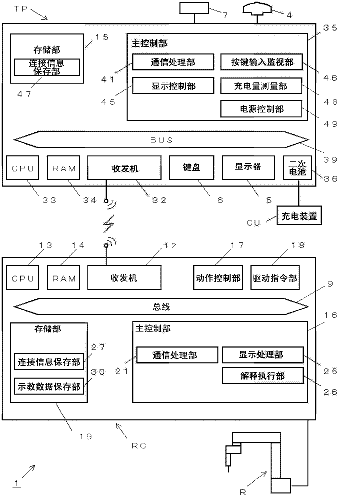
[0033] figure 1 It is a block diagram showing the robot control system according to the first embodiment of the present invention. The robot control system 1 includes a robot control device RC for controlling the motion of the robot R, a movable operation device TP for operating the robot R, and a charging device CU for charging the movable operation device TP.

[0034] First, the portable operation device TP will be described. The movable operating device TP is provided with: an emergency stop switch 4 for manually stopping the robot R in an emergency during automatic operation, a display 5 for displaying various data such as teaching data, inputting an inching feed signal and The keyboard 6 for teaching signals, the CPU 33 as a central processing unit, the RAM 34 as a temporary calculation area, the transceiver 32 for communicating with the robot control device RC, the secondary computer as the driving source of the movable operating device TP The battery 36, the power bu...

Embodiment approach 2

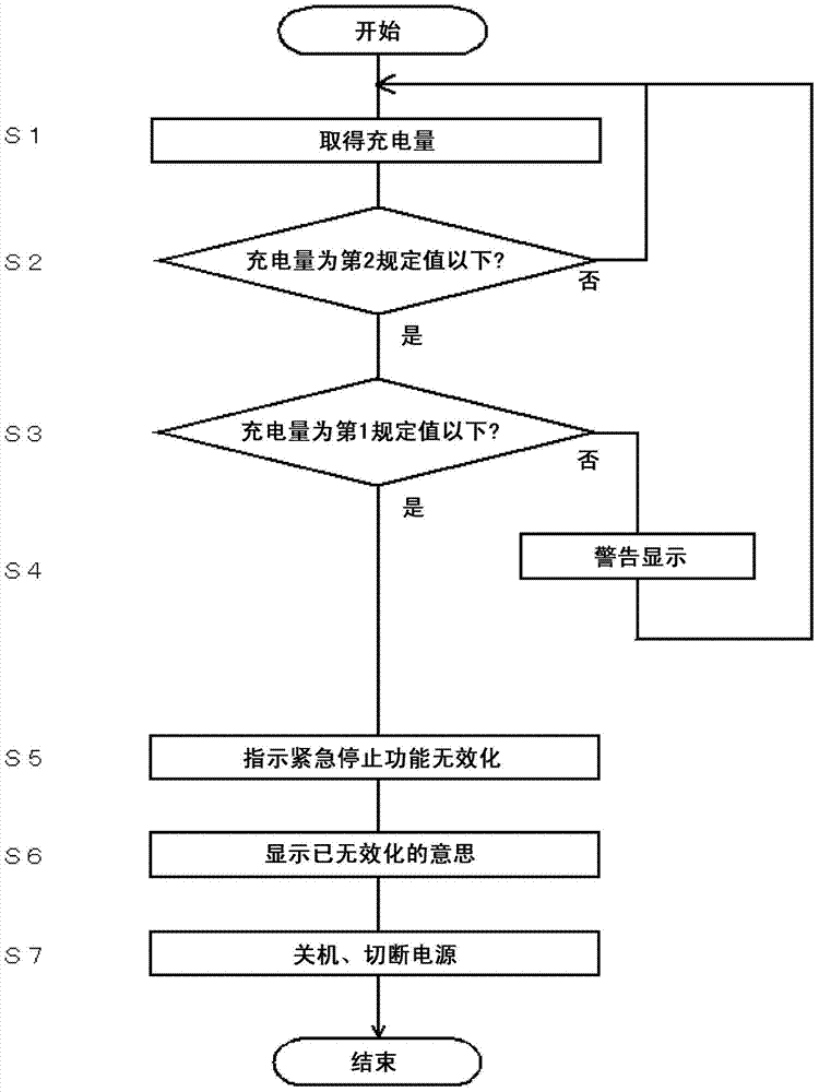
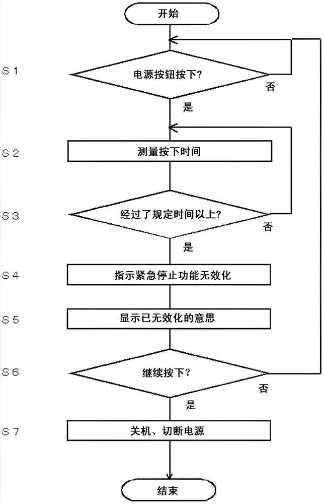
[0053] Next, Embodiment 2 of the present invention will be described. In Embodiment 1, the emergency stop function is automatically disabled in response to a decrease in the charge level, and shutdown processing and power supply cutoff processing are executed. In Embodiment 2, in addition to the above-mentioned processing according to the reduction of the charged amount, the above-mentioned processing is executed at the will of the operator regardless of the charged amount. More specifically, when the power button 7 is pressed for a long time while the power is supplied from the secondary battery 36, the emergency stop function is disabled sequentially according to the pressing time regardless of the charge amount of the secondary battery. and power cut off.

[0054] image 3 It is a flowchart showing the state of processing executed by the main control unit 35 of the portable operation device TP in the second embodiment.

[0055] In step S1 in the figure, it is checked whe...


PUM


Abstract

In automatic operation of a movable operating device when a robot control device is doing wireless communications for a long time, at the time point of the movable operation device changes the charging amount, the power supply is suddenly cut off and the robot is forced to stop work, so the automatic operation preferably cut off the wireless communication, but the back still has a long-time wireless communication. The invention of the robot control system (1) can do wireless communications in a movable operation device (TP) and a robot control device (RC). The movable operation device (TP) detects the movable operating device in the automatic operation (TP) and when it finds that the second battery charging amount (36) below a set value, it invalidates immediately and stops functioning. In the automatic operation, it is also possible to make use of a movable operation device of wireless communication (TP) , which significantly increases convenience, and for fear of an insufficient state of a second power discharge, it can emergently stop functioning, therefore, reducing risks for a production assembly line.

Description

technical field [0001] The present invention relates to a robot control system for transmitting and receiving various data between a robot control device and a movable operation device through wireless communication. Background technique [0002] In recent years, industrial robots that realize wireless communication between the robot control device that controls the motion of the robot and the mobile operating device that operates the robot have been proposed through network communication technology that conforms to the IEEE802 standard. Control system (see Patent Documents 1 and 2). Hereinafter, conventional robot control systems described in these patent documents will be described. [0003] Figure 4 It is a configuration diagram of a robot control system 51 that wirelessly communicates between a movable operating device and a robot control device. As shown in the figure, the robot control system 51 is roughly composed of a robot R that performs operations such as arc w...

Claims


Application Information

Patent Timeline
Patent Type & Authority Patents(China)
IPC IPC(8): B25J9/00
Inventor 谷信博
Owner DAIHEN CORP
Why Eureka
Try Eureka