Center shaft structure of delta robot

A technology of robot and shaft structure, which is applied in the direction of manipulators, program-controlled manipulators, manufacturing tools, etc., which can solve the problems of reduced operating precision, reduced efficiency, and large inertia, and achieve the effects of high-speed stable rotation, high precision and efficiency, and low cost.

Active Publication Date: 2014-07-02
杭州钱江机器人有限公司
View PDF8 Cites 7 Cited by
  • Summary
  • Abstract
  • Description
  • Claims
  • Application Information

AI Technical Summary

Problems solved by technology

Although this invention has the characteristics of high rigidity, the central axis of the robot still adopts a relatively conventional sleeve structure, that is, it includes a sleeve hinged with the drive platform, a telescopic rod hinged with the operating platform, and the telescopic rod is slid and inserted In the casing and the two are connected by splines, that is, the two are fixed in the circumferential direction, and in order to meet the strength requirements, both will be made of metal materials, such as stainless steel, and the weight is relatively large. During operation, the center shaft needs to be adjusted High-speed expansion and rotation, its large weight leads to large inertia, resulting in reduced efficiency and relatively low operating accuracy

Method used


Image

  • Center shaft structure of delta robot
  • Center shaft structure of delta robot
  • Center shaft structure of delta robot

Examples


Embodiment 1

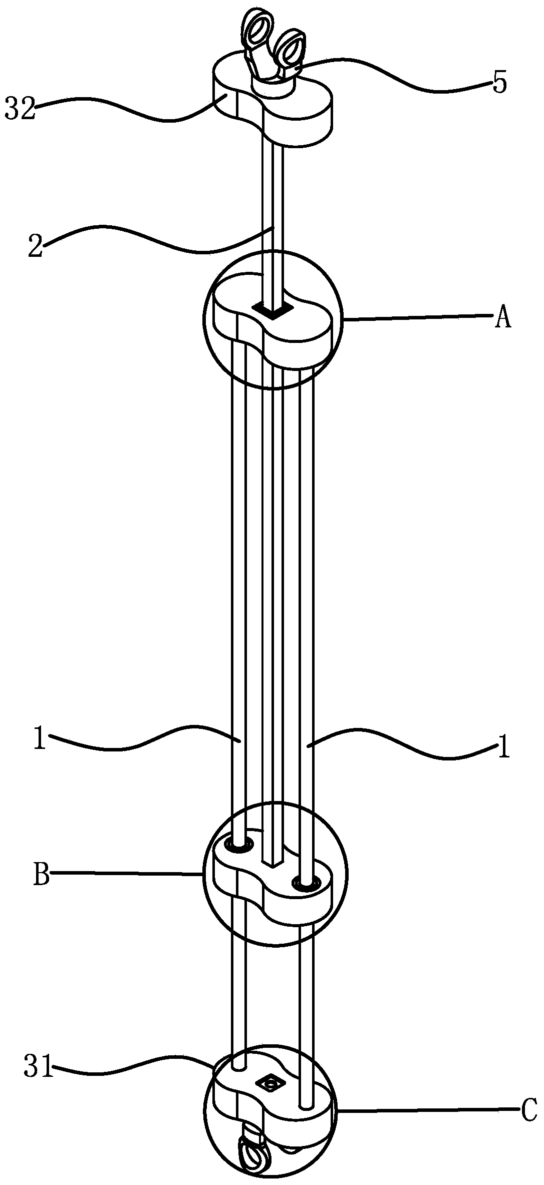
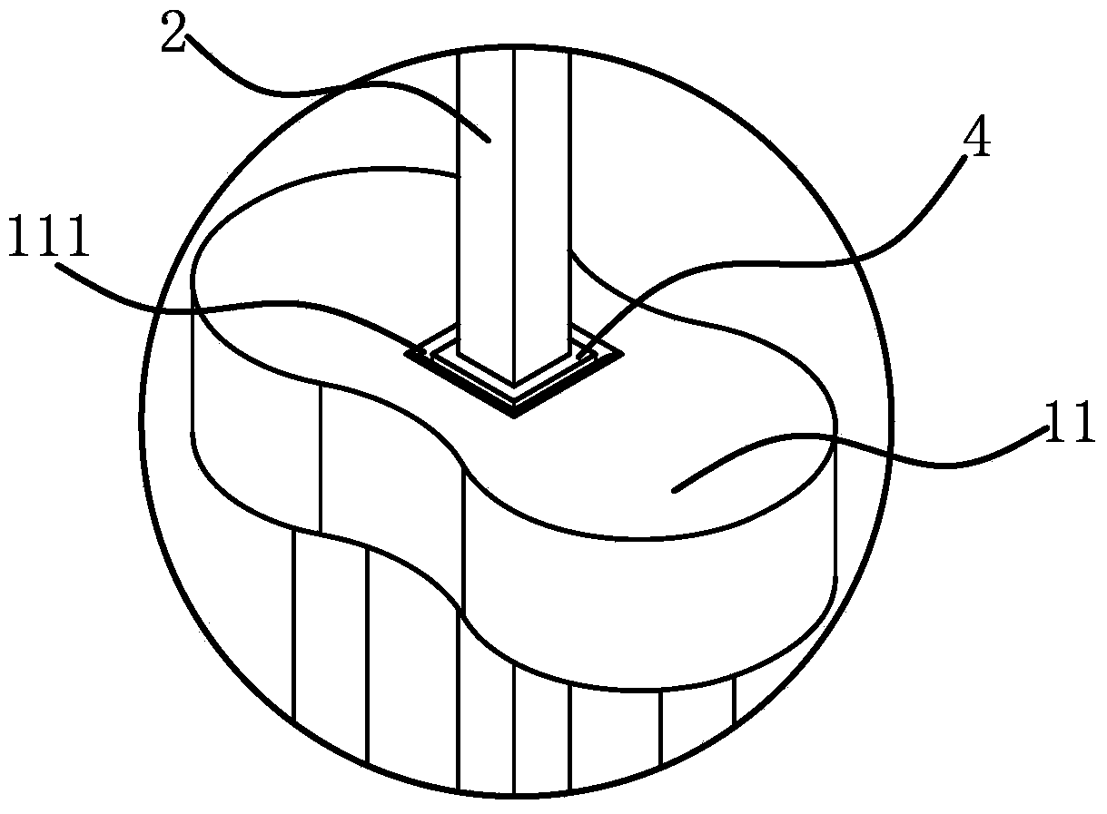
[0032] Such as figure 1 As shown, a central axis structure of a delta robot includes two robot driving arms 1 and a robot control arm 2, the two robot driving arms 1 are parallel to each other, and one end of the robot driving arm 1 is fixed by a fixed sleeve 31 Together, the other end is fixedly connected with a slider 11, the robot control arm 2 is parallel to the robot driving arm 1, and one end of the robot control arm 2 passes through the slider 11, and the robot control arm 2 and the slider 11 circle The direction is fixed, and it can slide axially relative to the slider one 11. The robot driving arm 1 and the robot control arm 2 are both made of carbon fiber material. The central axis of the delta robot needs to have the basic functions of expansion and rotation, and the structure of the central axis slides and connects the robot driving arm 1 and the robot control arm 2 through the slider 11. The robot driving arm 1 and the driving platform of the delta robot The robo...

Embodiment 2

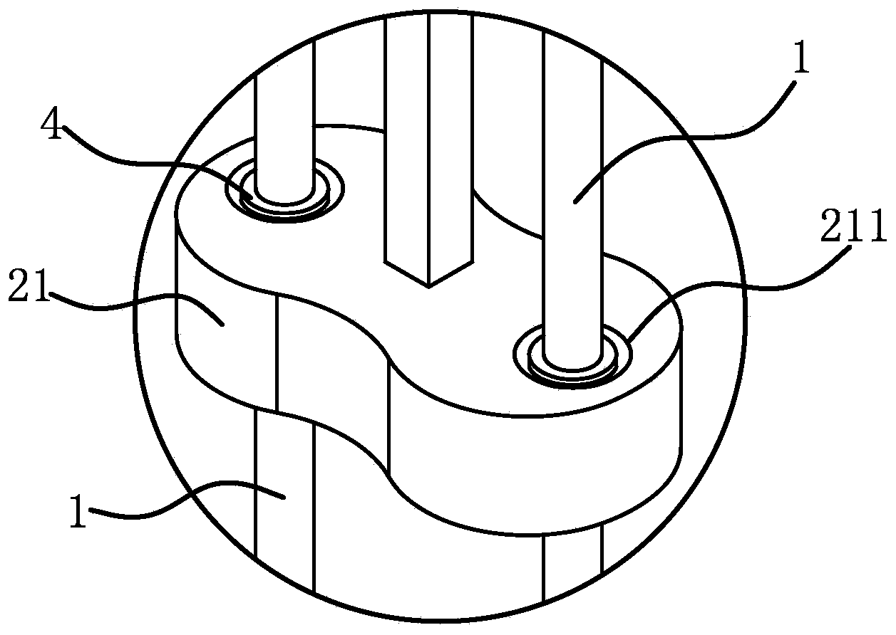
[0037] The structure of the polishing machine is basically the same as that of Embodiment 1, the difference is that Figure 5 , Image 6 As shown, the number of the robot driving arm 1 and the robot control arm 2 is two, and one end of the two robot control arms 2 is fixedly connected through the fixing sleeve 2 32, and the other end is fixedly connected with the slider 2 21, and the slider 1 11 There are two guide holes 211, and two guide holes 111 are opened on the slider 21. The two robot driving arms 1 respectively slide and penetrate in the two guide holes 211, and the two robot control arms 2 respectively slide and penetrate in the two guide holes. In the first guide hole 111, two robot driving arms 1 pass through two guide holes 211, which ensures the circumferential fixation between the slider two 21 and the two robot driving arms 1. Similarly, the two robot control arms 2 pass through Through the two guide holes 111, the circumferential fixation between the slider 11...

Embodiment 3

[0039] The structure of the polishing machine is basically the same as that of Embodiment 1, the difference is that Figure 7 , Figure 8 , Figure 9 As shown, the number of the robot driving arm 1 and the robot control arm 2 is three, and one end of the two robot control arms 2 is fixedly connected by the fixing sleeve 2 32, and the other end is fixedly connected with the slider 2 21, and the slider 1 11 is provided with There are three guide holes 211, and three guide holes 111 are opened on the slider 21, and the three robot driving arms 1 respectively slide through the three guide holes 211, and the three robot control arms 2 respectively slide through the three In the guide hole 111, obviously, more robot driving arms 1 and robot control arms 2 can make the overall strength higher, and in order to reduce the use of carbon fiber materials and reduce weight, under the premise of the same load capacity, the robot The driving arm 1 and the robot control arm 2 can be process...


PUM


Abstract

The invention discloses a center shaft structure of a delta robot and belongs to the technical field of mechanical equipment. The problems that inertia is high, efficiency is lower and operation accuracy is reduced due to the fact that the center shaft structure of an existing delta robot is large in structural weight are solved. The center shaft structure of the delta robot comprises at least two robot driving arms and at least one robot operation arm, the robot driving arms are parallel, one ends of the robot driving arms are fixedly connected together via a fixing sleeve, the other ends of the robot driving arms are fixedly connected with a first slider, one ends of the robot operation arms penetrate the first slider, the robot operation arms can slide relative to the slider along the self axial direction, and both the robot driving arms and the robot operation arms are made of carbon fiber materials. The center shaft of the delta robot is simple in structure and light in weight, thereby being low in inertia and high in efficiency when in running.

Description

technical field [0001] The invention belongs to the technical field of mechanical equipment and relates to a central axis structure of a delta robot. Background technique [0002] The Delta robot is a high-speed, light-load parallel robot. It generally captures the target object through teaching programming or a visual system. Three parallel servo axes determine the spatial position of the gripper center TCP to realize the transportation and processing of the target object. Delta robot is mainly used in the processing and assembly of food, medicine and electronic products. It is widely used in the market due to its light weight, small size, fast movement speed, accurate positioning, low cost and high efficiency. Delta robot assembly has three It is a typical three-degree-of-freedom parallel mechanism in space. The overall structure is precise and compact, and the driving parts are evenly distributed on the fixed platform. [0003] For example, the Chinese invention patent a...

Claims


Application Information

Patent Timeline
Patent Type & Authority Applications(China)
IPC IPC(8): B25J9/00B25J18/00
CPCB25J9/0051
Inventor 江加凯邓定红彭北京
Owner 杭州钱江机器人有限公司
Why Eureka
Try Eureka