
Wind turbine generator tower

A technology for wind turbines and machine towers, which is applied to wind turbine components, wind engines, and wind power generation. It can solve the problems of short service life of concrete structure design, high direct and indirect costs, and low life-cycle costs. Achieve the effect of avoiding the difficulty of high-altitude concrete construction, saving the amount of concrete, and clear force form

Inactive Publication Date: 2014-07-02
HUNAN UNIV
View PDF9 Cites 22 Cited by
  • Summary
  • Abstract
  • Description
  • Claims
  • Application Information

AI Technical Summary

Problems solved by technology

[0011] The purpose of the present invention is to solve the insufficient mechanical properties of the traditional all-steel tower tube and the independent expansion foundation structure system, the high direct and indirect costs of construction, the high risk of the construction process, the high maintenance cost, and the design service life of the concrete structure. Short, structure is difficult to meet the wind turbine installed capacity to large-scale development requirements and other issues, provide a wind turbine tower, give full play to the advantages of concrete and steel structure, reduce the direct cost of the structure itself, reduce structure maintenance costs, reduce Road construction costs, improving structural performance and safety, prolonging the service life of structures, and minimizing life-cycle costs

Method used


Image

  • Wind turbine generator tower
  • Wind turbine generator tower
  • Wind turbine generator tower

Examples


Embodiment 1

[0036] like figure 1 As shown, a wind power generator tower includes a concrete beam-slab foundation 1, a concrete bottom section tower tube 2, a steel transition tower section 3, and a steel tower section 4 from bottom to top. The concrete beam-slab foundation 1 and the prestressed concrete bottom section tower tube 2 are poured in sections using cast-in-place concrete to form a whole.

[0037] like figure 2 As shown, the concrete bottom section tower tube 2, the steel transition tower section 3, and the steel tower section 4 are all in the shape of hollow cylinders.

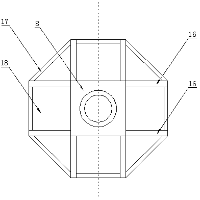
[0038] like image 3 As shown, the concrete beam slab foundation includes a base plate 18, a circular ring wall 8 located at the center of the top surface of the base plate 18, a side beam 17 arranged longitudinally on the outer edge of the base plate, a crossbeam 16 connecting the side beam 17 and the ring wall 8; The central axis of the wall 8 coincides with the vertical centerline of the tower tube 2 at ...

Embodiment 2

[0045] like Figure 9 , Figure 10 As shown, a wind power generator tower includes a concrete beam-slab foundation 1, a concrete bottom section tower tube 2, a steel transition tower section 3, and a steel tower section 4 from bottom to top. The concrete beam-slab foundation 1 and the prestressed concrete bottom section tower tube 2 are poured in sections using cast-in-place concrete to form a whole.

[0046] like Figure 11 , Figure 12 As shown, the concrete beam slab foundation includes a base plate 18, a circular ring wall 8 located at the center of the top surface of the base plate 18, a side beam 17 arranged longitudinally on the outer edge of the base plate, a crossbeam 16 connecting the side beam 17 and the ring wall 8; The central axis of the wall 8 coincides with the vertical centerline of the tower tube 2 at the concrete bottom section;

[0047] All the other structures are consistent with those of Example 1.


PUM


Abstract

The invention relates to a wind turbine generator tower. The wind turbine generator tower comprises a tower base and a steel tower section on the tower base, wherein a steel tower section lower flange plate is installed on the lower end surface of the steel tower section, the tower base is a concrete beam and slab base, a concrete base section tower barrel is arranged at the top of the concrete beam and slab base, a steel transition tower section is arranged between the concrete base section tower barrel and the steel tower section, the concrete base section tower barrel is connected with the concrete beam and slab base through a vertical pre-stress anchoring mechanism, and the steel tower section is connected with the steel transition tower section through a fastening mechanism. The wind turbine generator tower can give full play to the advantages of concrete and a steel structure, lower the direct manufacturing cost of the structure, reduce maintenance expenses of the structure, reduce road construction cost, improve the performance and safety of the structure, prolong the service life of the structure, and minimize the life cycle cost.

Description

technical field [0001] The invention relates to a wind power generator tower. Background technique [0002] Wind energy is a clean energy with a large resource reserve, and it is also one of the new energy types that are currently being developed at home and abroad. my country's wind resources are widely distributed, and there are good wind resources in the northwest, central and eastern coastal areas, so the development prospect of wind power is quite broad. Horizontal axis wind turbines are widely used in my country at this stage. Generally, all-steel towers are used. The foundation is an independent expansion foundation of reinforced concrete. The steel tower is directly connected to the foundation through a pre-embedded foundation ring. [0003] With the increase of the height of the tower, the thickness of the steel plate of the tower tube increases, and the production and manufacture of the steel tower becomes more and more difficult. The limitation of the road transp...

Claims


Application Information

Patent Timeline
Patent Type & Authority Applications(China)
IPC IPC(8): F03D11/00
CPCY02E10/722Y02P70/50
Inventor 许斌牛家兴
Owner HUNAN UNIV
Learn More