
Optical coherence domain polarization measurement device with optical path scanning position and speed correction function

A technology of optical path scanning and optical coherence, which is applied in the direction of testing optical performance, etc., to achieve the effect of simplifying the demodulation system and optical path, reducing cost and increasing difficulty

Active Publication Date: 2014-07-02
HARBIN ENG UNIV
View PDF9 Cites 23 Cited by
  • Summary
  • Abstract
  • Description
  • Claims
  • Application Information

AI Technical Summary

Problems solved by technology

However, the relevant literature of the previously published OCDP system did not discuss it.

Method used


Image

  • Optical coherence domain polarization measurement device with optical path scanning position and speed correction function
  • Optical coherence domain polarization measurement device with optical path scanning position and speed correction function
  • Optical coherence domain polarization measurement device with optical path scanning position and speed correction function

Examples


Embodiment Construction

[0046] In order to clearly illustrate the method and device of the optical path uniformity correction technology of the present invention, the present invention will be further described in conjunction with the embodiments and accompanying drawings, but the scope of protection of the present invention should not be limited by this.

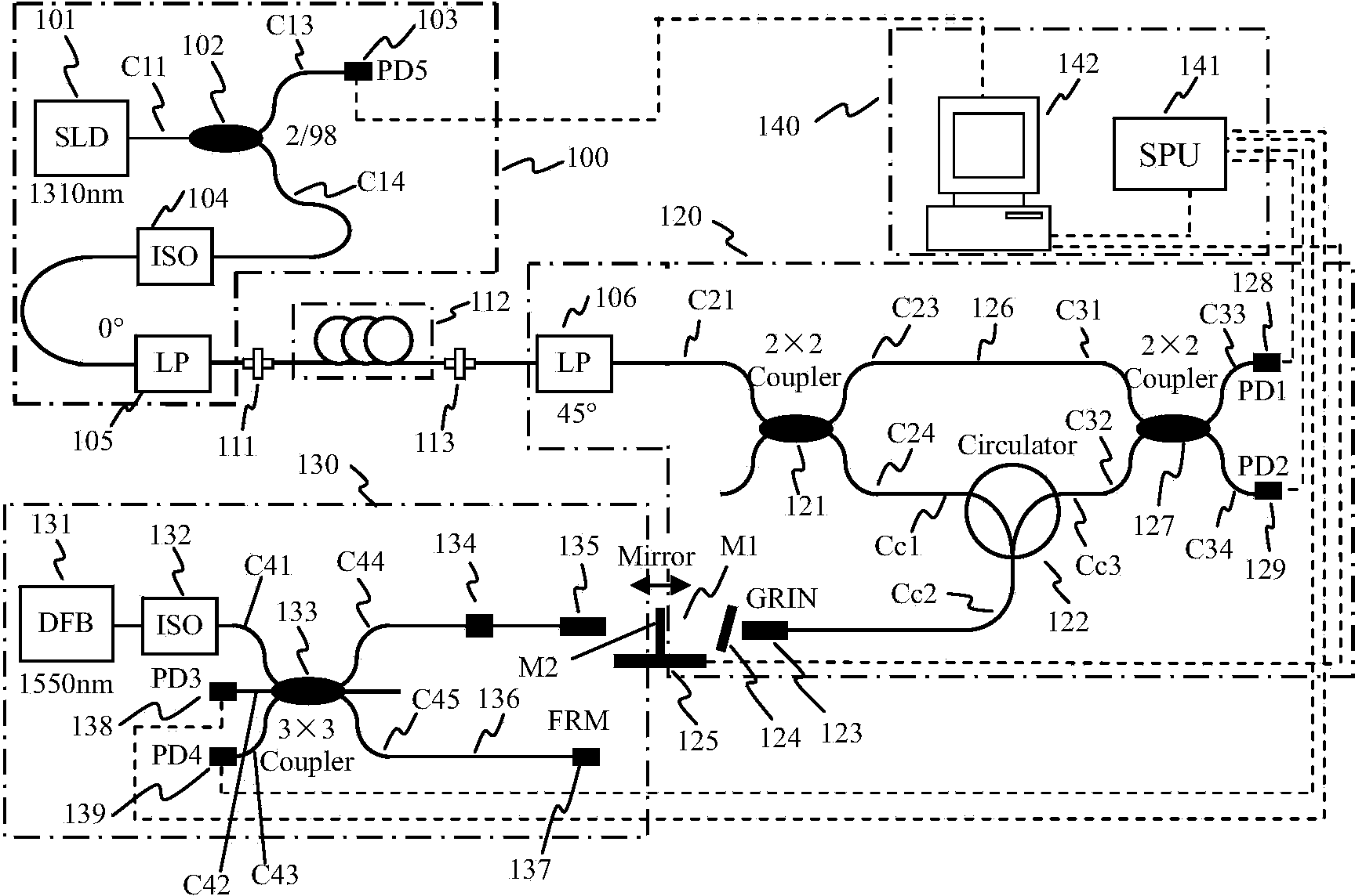
[0047] Optical coherence domain polarization measurement devices with optical path scanning position and velocity correction such as figure 1 As shown, the parameters of its main optoelectronic devices are as follows:

[0048] (1) The central wavelength of the broadband light source 101 is 1550nm, the half-spectrum width is greater than 45nm, the fiber output power is greater than 2mW, and the extinction ratio is greater than 6dB;

[0049] (2) The working wavelength of 1×2 coupler 102 is 1550nm, the extinction ratio is greater than 20dB, the insertion loss is less than 0.5dB, and the splitting ratio is 2 / 98;

[0050] (3) The operating wavelength...


PUM


Abstract

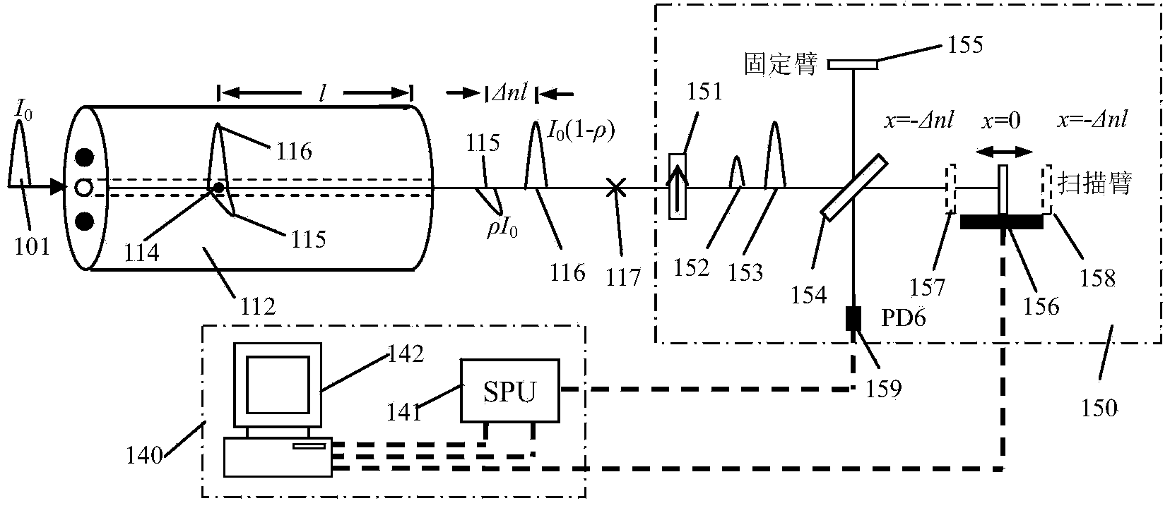
The invention provides an optical coherence domain polarization measurement device with an optical path scanning position and speed correction function. The optical coherence domain polarization measurement device comprises a wide-spectrum light source, a polarization device to be measured, an optical path correlator, an optical path scanning correction device and an interference signal detecting and processing device. The optical coherence domain polarization measurement device is characterized in that the added optical path scanning correction device is composed of a laser light source, an optical fiber 3*3 coupler, a movable reflection mirror in the optical path scanning device, a faraday rotating mirror and a photoelectric detector, the optical fiber 3*3 coupler conducts phase shifting on an interference signal to complete passive signal modulation of a Michelson type optical fiber interferometer, the faraday rotating mirror is used for eliminating polarization declination of the interferometer, and high-precision and rapid measurement of the optical path scanning position and the optical path scanning speed is achieved on the basis of a dual-detector correction algorithm. According to the device, precision and uniformity of optical path scanning are improved, and the device has the advantages of being small in size, high in measurement accuracy, capable of being easily combined with an existing application structure, and the like, and is widely applied to interference optical path scanning and testing for measuring the remote distance on the basis of white light interference.

Description

technical field [0001] The invention relates to an optical fiber measuring device, in particular to an optical coherent domain polarization measuring device with optical path scanning position and speed correction. Background technique [0002] Optical coherent domain polarization measurement technology (OCDP) is a high-precision distributed polarization coupling measurement technology. It is based on the principle of wide-spectrum light interference. It uses a scanning optical interferometer to perform optical path compensation to achieve interference between different polarization modes. The spatial position of the polarization crosstalk and the intensity of the polarization coupling signal are measured and analyzed with high precision, and then important parameters such as the extinction ratio and the beat length of the optical polarization device are obtained. As a very promising detection method for distributed optical polarization performance, OCDP technology is widely...

Claims


Application Information

Patent Timeline
Patent Type & Authority Applications(China)
IPC IPC(8): G01M11/02
Inventor 杨军吴冰苑勇贵闫德凯彭峰苑立波
Owner HARBIN ENG UNIV
Learn More