

Optical fiber collimator
A fiber collimator and collimator technology, which is applied in the field of optical fiber, can solve the problems of affecting the end face of the fiber collimator, collimator burnout, affecting usability, etc., to increase temperature stability and structural stability, and reduce pollution , Increase the effect of heat dissipation
- Summary
- Abstract
- Description
- Claims
- Application Information
AI Technical Summary
Problems solved by technology
Method used
Image

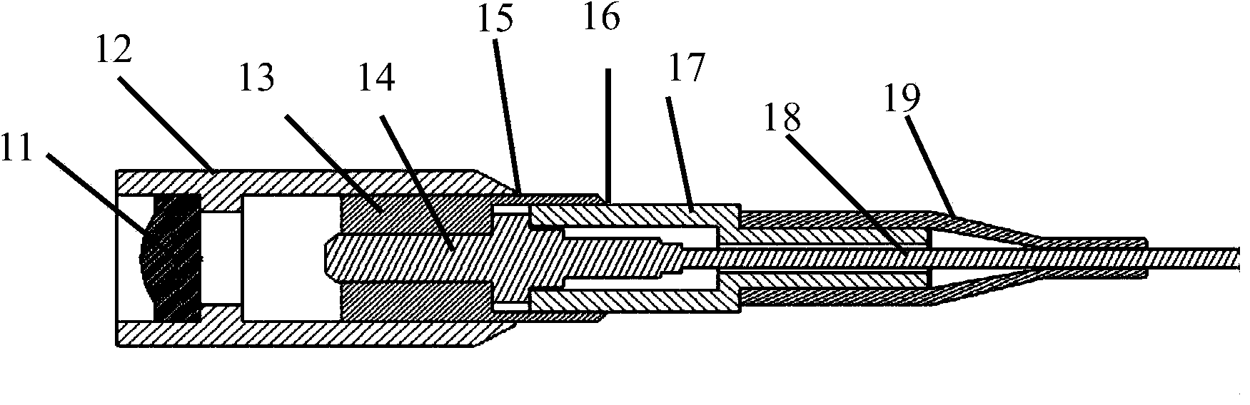
Examples
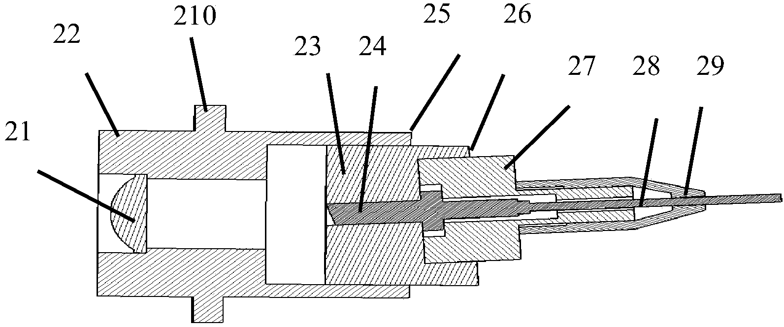
Embodiment 2
[0039] figure 2 It is Embodiment 2 of the present invention. The fiber collimator of this embodiment includes a collimator lens 21, a collimator structural member 22, an optical fiber ferrule fixing member 23, an optical fiber ferrule 24, an optical fiber ferrule fastener 27, and an optical fiber 28 And tail protection cover 29. The collimator structure 22 includes a fixing flange 210 . The difference from Embodiment 1 is that the light emitting end face of the optical fiber 28 in the fiber ferrule 24 is inclined, and the inner hole of the fiber ferrule fixing member 26 needs to have different inclination angles according to the inclination angle of the light emitting end face of the optical fiber 28 . This angle of inclination prevents light feedback from affecting the performance of the light source in high-power operation. When using a polarization-maintaining fiber, this angle can also make the polarization direction of the output light of the collimator relative to the ...
PUM
 Abstract
Description
Claims
Application Information