Aerial photographing type rotor craft control system

A rotorcraft and control system technology, applied in the field of aerial rotorcraft control systems, can solve the problems of weak anti-gyro effect, poor anti-interference, poor stability, etc., and achieve strong anti-gyro effect, high integration and good stability Effect

Inactive Publication Date: 2014-07-02
WUHAN UNIV OF SCI & TECH
View PDF3 Cites 4 Cited by
  • Summary
  • Abstract
  • Description
  • Claims
  • Application Information

AI Technical Summary

Problems solved by technology

[0003] In a word, the existing aerial photography rotorcraft has the following technical defects in practical application: poor anti-interference, low load-to-weight ratio, poor stability, and weak anti-gyroscope effect

Method used


Image

  • Aerial photographing type rotor craft control system
  • Aerial photographing type rotor craft control system
  • Aerial photographing type rotor craft control system

Examples


Embodiment 1

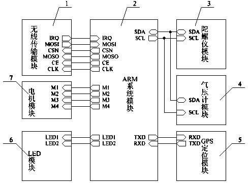
[0040] A control system for an aerial photography type rotorcraft. The aerial photography type rotorcraft described in this embodiment is an aerial photography type quadrotor aircraft, and the control system of the aerial photography type quadrotor aircraft is as follows: figure 1As shown, it includes a wireless transmission module 1 , an ARM system module 2 , a gyroscope module 3 , a barometer module 4 , a GPS positioning module 5 , an LED module 6 and a motor module 7 . The output terminals CSN, MOSO, CE and CLK of the ARM system module 2 are connected to the input terminals CSN, MOSO, CE and CLK of the wireless transmission module 1, and the input terminals IRQ and MOSI of the ARM system module 2 are connected to the output terminals of the wireless transmission module 1. IRQ and MOSI are connected correspondingly; the output terminal SCL of the ARM system module 2 is connected to the input terminal SCL of the gyroscope module 3, and the bidirectional input / output terminal ...

Embodiment 2

[0064] A control system for an aerial photography type rotorcraft. The aerial photography type rotorcraft described in this embodiment is an aerial photography type single rotor aircraft, and the aerial photography type single rotor aircraft control system except the following technical parameters, all the other are the same as embodiment 1:

[0065] The output terminal M1 of the ARM system module 2 is connected to the input terminal M1 of the motor module 7 .

[0066] The output terminal M1 of the chip U1 is connected to the input terminal M1 of the motor module 7 .

[0067] The motor module 7 is composed of a motor sub-module, and the motor sub-module is connected to the input terminal M1 of the motor module (7).

[0068] The input terminal M1 of the motor module 7 is connected to the output terminal M1 of the ARM system module 2 .

Embodiment 3

[0070] A control system for an aerial photography type rotorcraft. The aerial photography type rotorcraft described in this embodiment is an aerial photography type dual rotor aircraft, and the aerial photography type dual rotor aircraft control system is except the following technical parameters, all the other are the same as embodiment 1:

[0071] The output terminals M1 and M2 of the ARM system module 2 are correspondingly connected to the input terminals M1 and M2 of the motor module 7 .

[0072] The output terminals M1 and M2 of the chip U1 are correspondingly connected to the input terminals M1 and M2 of the motor module 7 .

[0073] The motor module 7 is composed of two mutually independent motor sub-modules, each motor sub-module is the same, and each motor sub-module is connected to the corresponding input terminals M1 and M2 of the motor module (7).

[0074] The input terminals M1 and M2 of the motor module 7 are correspondingly connected to the output terminals M1 ...


PUM


Abstract

The invention relates to an aerial photographing type rotor craft control system. According to the technical scheme, an ARM system module (2) is connected with a wireless transmission module (1), a gyro module (3), a barometer module (4), a GPS positioning module (5), an LED module (6) and a motor module (7); the ARM system module (2) is internally provided with control software of the craft control system. The control software and hardware of the craft control system act together, and the aerial photographing type rotor craft control system has the advantages of being good in anti-interference performance, high in bearing ratio, good in stability and high in gyroscopic effect resistance. The aerial photographing type rotor craft control system is suitable for being used for high altitude shooting and low altitude shooting equipment in various industries.

Description

technical field [0001] The invention belongs to the technical field of aircraft control systems. In particular, it relates to an aerial photographing type rotorcraft control system. Background technique [0002] The existing aerial photography rotorcraft technology is relatively mature, and can complete fixed-point hovering, low-speed and low-altitude flight, vertical take-off and landing, and indoor flight, and these actions cannot be completed by some fixed-wing aircraft. Although the aerial photography rotorcraft can be applied to on-the-spot shooting in multiple occasions, such as forests, crops and areas where poisonous and harmful obstacles are inaccessible to personnel. But its disadvantages are: it will show strong nonlinear characteristics in the case of high dynamic flight; it will be affected by the interference of airflow and various parameter perturbations during the flight; the load capacity is limited, and it is impossible to carry high-precision navigation ...

Claims


Application Information

Patent Timeline
Patent Type & Authority Applications(China)
IPC IPC(8): G05B19/04
Inventor 李劲松杨君林森张莹刘友才张黄学
Owner WUHAN UNIV OF SCI & TECH
Why Eureka
Try Eureka