
Diode lead wire welding assembly method and device

A technology of lead welding and assembly method, which is applied in the manufacturing of electrical components, electric solid-state devices, semiconductor/solid-state devices, etc., can solve the problems of unsatisfactory diode lead welding, unsuitable for mass production, and labor-intensive labor, etc. Achieve the effect of relaxing the labor tension, high quality lead assembly, and reduced labor intensity

Active Publication Date: 2014-07-02
GUIZHOU YAGUANG ELECTRONICS TECH
View PDF4 Cites 12 Cited by
  • Summary
  • Abstract
  • Description
  • Claims
  • Application Information

AI Technical Summary

Problems solved by technology

[0002] At present, in the production of existing diodes, when using a welding device to weld the lead wires of the diode to the die, it is generally used to manually place the lead wires one by one on the die mounted on the tube base, and then proceed. Welding, every time a die is soldered, put another lead on the die of another tube base and then solder, this way of placing the leads one by one on the die mounted on the tube base , there is not only the problem of low work efficiency, but also the problem that the labor load of the workers is large and the workers' attention must be highly concentrated, which makes it easy for the workers to fatigue and produce substandard products
Therefore the existing mode of this diode lead wire welding is very unsatisfactory, does not adapt to the needs of large-scale production very much

Method used


Image

  • Diode lead wire welding assembly method and device
  • Diode lead wire welding assembly method and device
  • Diode lead wire welding assembly method and device

Examples


Embodiment Construction

[0013] The present invention will be further described in detail below in conjunction with the accompanying drawings and embodiments.

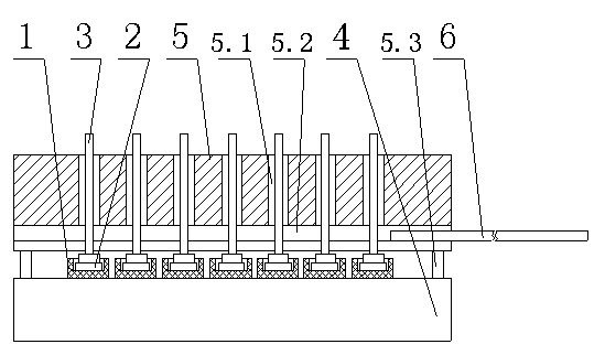
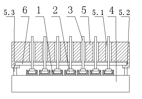
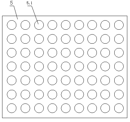
[0014] Embodiments of the present invention: when the lead wire 3 of the diode is welded with the tube core 2 of the diode through a traditional welding device, a diode lead wire welding assembly method of the present invention can be used for implementation, such as figure 1 As shown, the method is to pre-place the sockets 1 of the diode cores 2 in a matrix arrangement in the soldering assembly tray 4 (the soldering assembly tray 4 can directly adopt the soldering assembly tray in the prior art), And according to the traditional method, put a piece of solder on the upper and lower sides of each die 2, and then make a lead assembly plate 5 with a through hole 5.1. The diameter of the through hole 5.1 should be 0.1 to 0.3 larger than the diameter of the base of the lead 2. mm, the through holes 5.1 arranged on the lead assembly tray 5 are arran...


PUM


Abstract

The invention discloses a diode lead wire welding assembly method and device. The method is characterized by placing tube sockets equipped with tube cores of diodes in a welding assembly disc in a matrix arrangement manner in advance, the upper and lower surface of each tube core are respectively placed with a welding flake; then, producing a lead wire assembly disc provided with through-holes, and arranging a movable baffle plate capable of blocking the bottom ends of all through-holes under the lead wire assembly disc; putting one lead wire into each through-hole of the lead wire assembly disc; after placing the lead wire assembly disc placed with the lead wires on the welding assembly disc, withdrawing the movable baffle plate, so that the lead wire in each through-hole drops onto the welding flake of each tube core respectively; and therefore, the welding assembly disc can be sent to a welding device to carry out welding of the lead wires and the tube cores of the diodes. The diode lead wire welding assembly method and device have the advantages of high work efficiency and small labor intensity; the work strain degree can be effectively reduced; and the lead wire assembly quality can be guaranteed to accord with requirements and the like.

Description

technical field [0001] The invention relates to a method and device for welding and assembling a diode lead wire, belonging to the technical field of diode production. Background technique [0002] At present, in the production of existing diodes, when using a welding device to weld the lead wires of the diode to the die, it is generally used to manually place the lead wires one by one on the die mounted on the tube base, and then proceed. Welding, every time a die is soldered, put another lead on the die of another tube base and then solder, this way of placing the leads one by one on the die mounted on the tube base , not only has the problem of low work efficiency, but also has the problem of a large amount of labor for workers and requires a high degree of concentration of workers' attention, which can easily cause workers to fatigue and produce substandard products. Therefore, the existing method of welding the diode leads is not ideal, and is not suitable for mass pro...

Claims


Application Information

Patent Timeline
IPC IPC(8): H01L21/60
CPCH01L24/01H01L24/85H01L24/75H01L24/78H01L24/81H01L2224/81H01L2224/85
Inventor 杨华林笋
Owner GUIZHOU YAGUANG ELECTRONICS TECH
Learn More