Base station dormancy method based on energy saving and equipment

A technology for base station equipment and base stations, which is applied in the field of energy-saving base station dormancy, can solve the problems of not providing micro base stations, unable to process energy-saving micro base stations, etc., and achieve the effect of low energy consumption

Active Publication Date: 2014-07-02
CHINA MOBILE COMM GRP CO LTD
View PDF3 Cites 20 Cited by
  • Summary
  • Abstract
  • Description
  • Claims
  • Application Information

AI Technical Summary

Problems solved by technology

[0005] In the prior art, there is no solution for when the micro base station in the active state can go to sleep to realize energy saving, so it is impossible to perform energy-saving processing on the micro base station in the active state

Method used


Image

  • Base station dormancy method based on energy saving and equipment
  • Base station dormancy method based on energy saving and equipment
  • Base station dormancy method based on energy saving and equipment

Examples


Embodiment 1

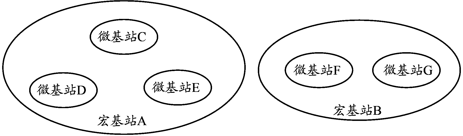
[0027] Embodiment 1 of the present invention provides a base station dormancy method based on energy saving. The method is applied to a system including a macro base station and multiple micro base stations. The multiple micro base stations are all within the coverage of the macro base station. figure 1 It is a schematic diagram of the application scenario of the embodiment of the present invention. Within the coverage of macro base station A, there are micro base stations C, micro base stations D, and micro base stations E; within the coverage of macro base station B, there are micro base stations F and micro base station G.

[0028] In the embodiment of the present invention, the micro base station can be in one of the following three states: sleep state, detection state and activation state; in the sleep state, the micro base station stops radio frequency transmission; in the detection state, the micro base station transmits pilot Or a reference signal or a broadcast signal,...

Embodiment 2

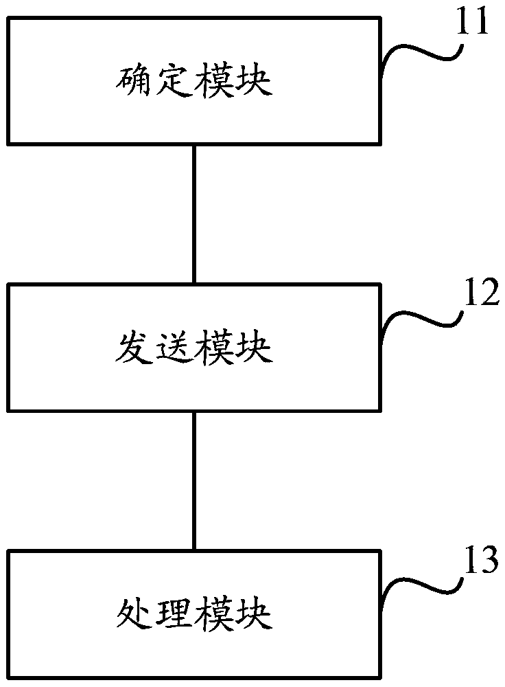
[0048] Based on the same inventive concept as the above method, an embodiment of the present invention also provides a base station device, which is applied to a system including a macro base station and multiple micro base stations, and the multiple micro base stations are all covered by the macro base station range, such as image 3 As shown, the base station equipment includes:

[0049] A determining module 11, configured to determine that the traffic volume of the device is lower than a preset first threshold;

[0050] A sending module 12, configured to send a measurement request message to other micro base stations when the device is in an active state and the traffic volume of the device is lower than a preset first threshold;

[0051] When the other micro base station allows the terminal device served by the device to switch to the other micro base station, notify the terminal device served by the device to switch to the other micro base station;

[0052] The processi...

Embodiment 3

[0055] Based on the same inventive concept as the above method, an embodiment of the present invention also provides a base station device, which is applied to a system including a macro base station and multiple micro base stations, and the multiple micro base stations are all covered by the macro base station range, such as Figure 4 As shown, the base station equipment includes:

[0056] The receiving module 21 is configured to receive a measurement request message from the micro base station when the traffic volume of the micro base station in the activated state is lower than a preset first threshold;

[0057] The determining module 22 is configured to determine that the device allows the terminal devices served by the micro base station to be handed over to the device, and all terminal devices served by the micro base station are to be handed over to the device.


PUM


Abstract

The invention discloses a base station dormancy method based on energy saving and a piece of equipment. The method is applied to a system including a macro base station and a plurality of micro base stations, wherein the plurality of micro base stations are in the coverage of the macro base station. The method comprises the following steps: when a micro base station in an activated state determines that the service volume of the equipment is lower than a preset first threshold, the micro base station sends a measurement request message to the other micro base stations; when the other micro base stations allow terminal equipment served by the micro base station to be switched to the other micro base stations, the micro base station notifies terminal equipment served by the equipment to be switched to the other micro base stations; and the micro base station enters a dormant state after all the terminal equipment served by the equipment is switched to the other micro base stations. According to the embodiment of the invention, when the service volume of the micro base station in an activated state is too low, all the terminal equipment served by the micro base station is switched to the other micro base stations, and the micro base station is made dormant so that energy-saving processing can be performed on the micro base station in an activated state.

Description

technical field [0001] The present invention relates to the technical field of communications, in particular to an energy-saving-based dormancy method and equipment for a base station. Background technique [0002] In the mobile communication network, due to the difference in time domain and region of service distribution, in the actual network coverage, there are often situations where macro base stations (ie, large base stations) and micro base stations (ie, small base stations) co-cover, and micro base stations are in the within the coverage of the macro base station. Such as figure 1 As shown, it is a schematic diagram of the common coverage of the macro base station and the micro base station. The macro base station has a macro base station A and a macro base station B, and the micro base station has a micro base station C, a micro base station D, a micro base station E, a micro base station F, and a micro base station G; Within the coverage of station A, there are mi...

Claims


Application Information

Patent Timeline
Patent Type & Authority Applications(China)
IPC IPC(8): H04W36/08H04W36/30H04W52/02
CPCY02B60/50Y02D30/70
Inventor 李琴韩双锋
Owner CHINA MOBILE COMM GRP CO LTD
Why Eureka
Try Eureka