Supercharge Your Innovation With Domain-Expert AI Agents!

Positioning mechanism in forging die

A positioning mechanism and two positioning technology, applied in forging/pressing/hammering machinery, manufacturing tools, forging/pressing/hammer devices, etc., can solve problems such as personal safety cannot be guaranteed, forging defects, low deformation resistance, etc. The effect of reducing manual operation time and labor intensity, reducing contact time, and improving forming performance

Active Publication Date: 2016-04-13
SUZHOU KUNLUN HEAVY EQUIP MFG
View PDF5 Cites 0 Cited by
  • Summary
  • Abstract
  • Description
  • Claims
  • Application Information

AI Technical Summary

Problems solved by technology

[0004] First: It takes a long time. Closed die forging is also called flashless die forging, which belongs to near-net shape. When forging, the blank shape is required to be reasonable and can be accurately positioned in the die cavity. When the cross-sectional size of the blank is much smaller than the cross-section of the concave mold cavity When sizing, it is easy to have material deviation or pouring. Manual positioning requires repeated operation and positioning, which often takes more than a few minutes. As we all know, the higher the temperature of the blank within a certain range, the better the plasticity and the lower the deformation resistance. During the positioning process, the billet is in contact with air and other media, the temperature of the billet decreases, the plasticity deteriorates and a large amount of oxide skin is formed. If the billet cannot be positioned accurately, the light one will cause forging defects or even be scrapped, and the severe one will damage the mold;
[0005] Second: Personal safety cannot be guaranteed. The temperature of the billet during hot forging is as high as 1000°C, and the operator works in a high-temperature environment for a long time, which is prone to safety accidents

Method used


Image

  • Positioning mechanism in forging die

Examples


Embodiment

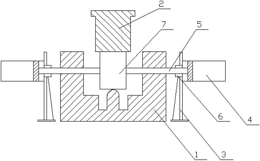
[0012] Embodiment: a positioning mechanism in a forging die, the first and second perforations are respectively provided on the two opposite side walls of the concave die 1 of the forging die, and the first and second positioning mechanisms are fixed on the outside of the forging die. The positioning mechanism is provided with a positioning rod 5 that can be fed horizontally in the axial direction, and the positioning rods 5 of the first and second positioning mechanisms can be slidably inserted into the first and second perforations of the forging die. The positioning mechanism is distributed on two opposite sides of the forging die in a symmetrical state, and they all include a support seat 3, a cylinder 4 and a positioning rod 5. The support seat 3 is relatively fixed and positioned with the forging die, and the cylinder body of the cylinder 4 is fixed on the support seat 3. On the top, the positioning rod 5 is fixedly connected with the piston of the cylinder 4. In addition...


PUM


Abstract

The invention discloses a location mechanism in a forging die. A first through hole and a second through hole are formed in two opposite lateral walls of a recessed die of the forging die. A first location mechanism and a second location mechanism are fixedly arranged on the outside of the forging die, a location rod capable of being fed horizontally in the axial direction is arranged on the first location mechanism and the second location mechanism respectively, and the location rods on the first location mechanism and the second location mechanism can be inserted in the first through hole and the second through hole of the forging die in a sliding mode. Accurate location of a blank at the center of the recessed die is achieved, the location speed is high, the contact time of the blank and media like air is reduced after the blank leaves a furnace, the blank formation performance can be effectively improved, the forge piece defective rate is reduced, and die abrasion is reduced. A cylinder location device allows automatic operation, manual operation time and labor intensity are greatly reduced, and safety hazards are greatly reduced.

Description

technical field [0001] The invention relates to a forging die, in particular to an internal positioning mechanism of the forging die. Background technique [0002] The existing method is to locate the position of the hot blank in the mold through mechanical operation and manual visual inspection, so as to reduce the probability of material deviation or dumping as much as possible. [0003] Disadvantages of existing methods: [0004] First: It takes a long time. Closed die forging is also called flashless die forging, which belongs to near-net shape. When forging, the blank shape is required to be reasonable and can be accurately positioned in the die cavity. When the cross-sectional size of the blank is much smaller than the cross-section of the concave mold cavity When sizing, it is easy to have material deviation or pouring. Manual positioning requires repeated operation and positioning, which often takes more than a few minutes. As we all know, the higher the temperature...

Claims


Application Information

Patent Timeline
Patent Type & Authority Patents(China)
IPC IPC(8): B21J13/02
Inventor 黄建华刘英贵张晓松陈燕刘卫军鲁海东王光明
Owner SUZHOU KUNLUN HEAVY EQUIP MFG
Features
  • R&D
  • Intellectual Property
  • Life Sciences
  • Materials
  • Tech Scout
  • Unparalleled Data Quality
  • Higher Quality Content
  • 60% Fewer Hallucinations
Learn More