
Underwater pouring type tubular column with retaining wall and construction method thereof

A construction method and pouring technology, which is applied in construction, foundation structure engineering, sheet pile walls, etc., can solve the problems of difficult splicing construction at the joints of each joint, difficult control of grouting quality, and difficult transportation of prefabricated parts. The construction period and stiffness-to-mass ratio are good, and the effect of improving construction efficiency

Active Publication Date: 2014-07-09
ANHUI TRANSPORTATION HLDG GRP CO LTD
View PDF6 Cites 1 Cited by
  • Summary
  • Abstract
  • Description
  • Claims
  • Application Information

AI Technical Summary

Problems solved by technology

For this process, in addition to the difficulties in transporting prefabricated parts at the construction site, the large hoisting equipment, and the difficulty in sinking the prefabricated parts, there are also the following points that are difficult to control: after sinking, the whole body is easy to tilt due to the residue at the bottom; Splicing construction at joints is difficult; the grouting process is complicated, the quality of grouting is difficult to control, and the construction period is long and the cost is high

Method used


Image

  • Underwater pouring type tubular column with retaining wall and construction method thereof
  • Underwater pouring type tubular column with retaining wall and construction method thereof
  • Underwater pouring type tubular column with retaining wall and construction method thereof

Examples


Embodiment Construction

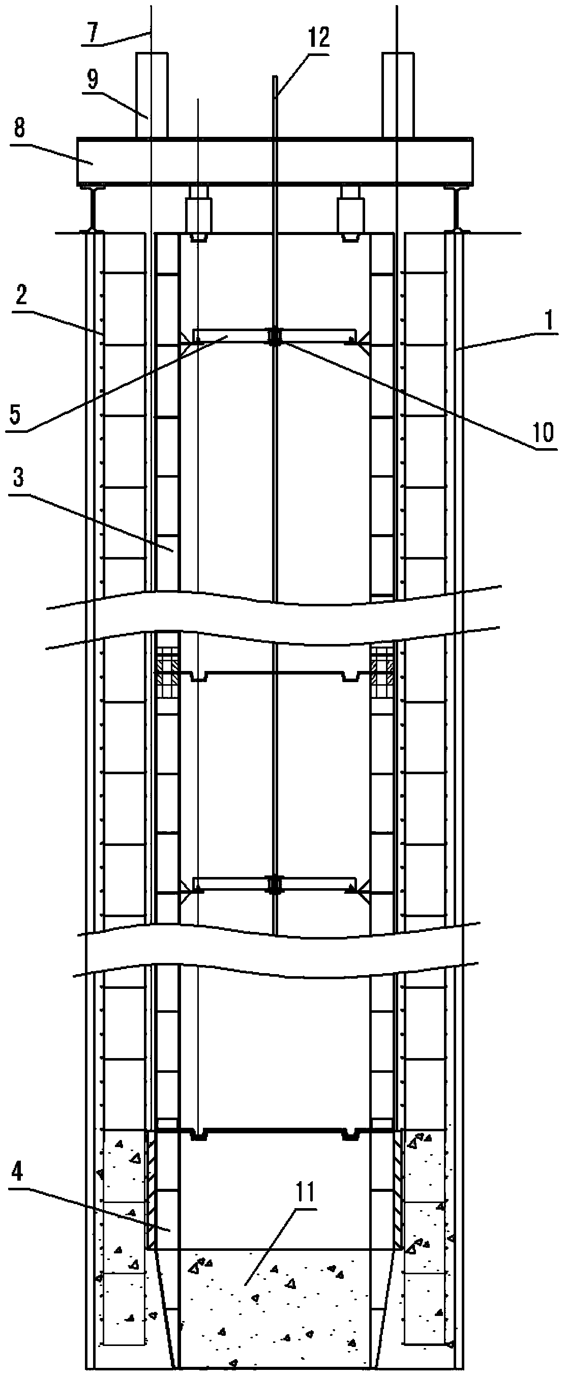
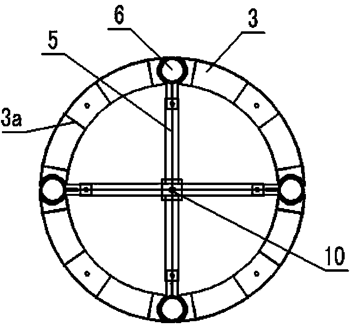
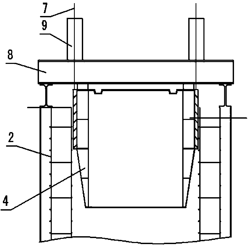
[0033] see figure 1 , figure 2 , image 3 , Figure 4 , Figure 5 and Figure 6 In this embodiment, the structural form of the internal mold system for constructing an underwater pouring pipe column with retaining walls is:

[0034] Such as figure 1 As shown, it includes a steel structure bottom section formwork 4, on the bottom section formwork 4, the prefabricated inner formwork 3 of each section is assembled section by section; the prefabricated inner formwork 3 of each section is a fully enclosed formwork that can obtain buoyancy in water Steel structure hollow buoy structure, after releasing the locking of the inner formwork, the inner formwork 3 of each segment can be recovered by floating up by buoyancy; the bottom section formwork 4 is poured in the concrete bottom cover 11 of the column hole for positioning.

[0035] Such as figure 2 and Figure 5 As shown, the prefabricated inner formwork 3 of each segment is assembled from tile templates; in the prefabrica...


PUM


Abstract

The invention discloses an underwater pouring type tubular column with a retaining wall and a construction method thereof. The underwater pouring type tubular column is characterized in that underwater quick set materials are used for pouring a retaining wall layer in a hole along the inner wall of the hole from bottom to top to form a retaining wall hole, and a cylindrical reinforcement cage is placed downwards into the retaining wall hole; a steel structure conical bottom joint formwork is placed downwards to the cylinder of the reinforcement cage, and all segments of prefabricated inner formworks are assembled one by one from bottom to top to form an inner mold; bottom sealing concrete is poured into the retaining wall hole to form a concrete bottom plate so that the retaining wall hole can become a bottom-sealed annular cylinder; in the bottom-sealed annular cylinder, the retaining wall layer serves as an outer mold, tube body concrete pouring is carried out between the outer mold and the inner mold, and after the strength of the tube body concrete meets the requirement, all segments of the prefabricated inner formworks are taken out from top to bottom, and the construction of the underwater pouring type tubular column with the retaining wall is finished. The underwater pouring type tubular column can be effectively applied to constructing engineering, bridge buildings and water conservancy project structures, and the construction efficiency is improved.

Description

technical field [0001] The invention relates to a foundation cast-in-place construction method in civil engineering, bridge house construction and hydraulic structures. Background technique [0002] The existing caisson and immersed tube foundation construction adopts the method of segmental prefabricated components, then relying on self-weight or auxiliary measures to connect heights and subsidence, and then carry out grouting treatment. For this process, in addition to the difficulties in transporting prefabricated parts at the construction site, the large hoisting equipment, and the difficulty in sinking the prefabricated parts, there are also the following points that are difficult to control: after sinking, the whole body is easy to tilt due to the residue at the bottom; The splicing construction at joint joints is difficult; the grouting process is complicated, the quality of grouting is difficult to control, and the construction period is long and the cost is high. T...

Claims


Application Information

Patent Timeline
Patent Type & Authority Applications(China)
IPC IPC(8): E02D5/40E02D5/66
Inventor 殷永高孙敦华张立奎吕奖国赵先民赵公明郑伟峰朱星虎明昕葛德宏
Owner ANHUI TRANSPORTATION HLDG GRP CO LTD
Learn More