Hub reduction gear

A wheel-side deceleration and wheel-hub technology, applied in gear transmission, differential transmission, control device, etc., can solve problems such as oil leakage, short service time, broken teeth, etc.

Active Publication Date: 2014-07-09
CHANGZHOU RUITAI ENG MASCH CO LTD +1
View PDF7 Cites 11 Cited by
  • Summary
  • Abstract
  • Description
  • Claims
  • Application Information

AI Technical Summary

Problems solved by technology

Due to the harsh working conditions, the service time is generally shor

Method used


Image

  • Hub reduction gear
  • Hub reduction gear

Examples


Embodiment Construction

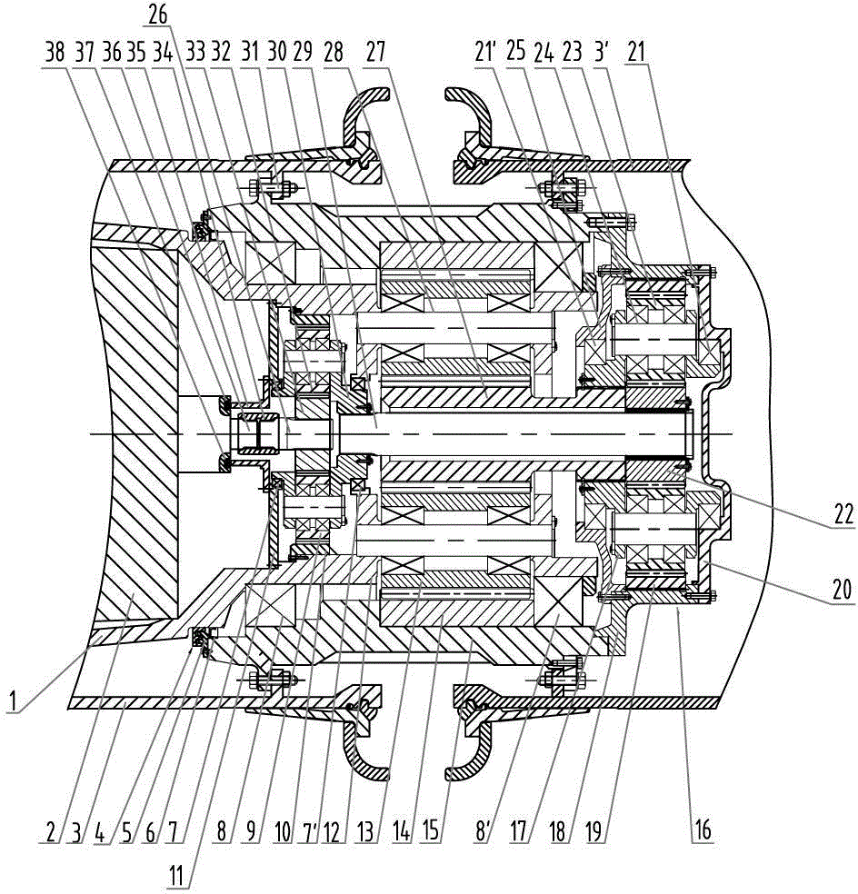
[0014] Such as figure 1 As shown, a wheel speed reduction device of the present invention includes a frame 1, a drive motor 2, a first-stage planetary mechanism 32, a second-stage differential mechanism 24, a third-stage fixed-axis wheel train mechanism 28, a wheel hub 15 and a rim 3, 3', wherein the drive motor 2 is fixedly connected to the frame 1, the output shaft 36 of the drive motor is connected to one end of the spline sleeve 34, and the primary planetary mechanism 32 includes a primary sun gear spindle 26, a primary sun gear 33 , a primary planet carrier 30, a primary planetary gear 9 and a primary ring gear 10, the primary sun gear mandrel 26 is connected to the other end of the spline sleeve 34, and the primary sun gear 33 is fixed on the primary sun gear On the wheel spindle 26, the primary sun gear 33 meshes with the primary planetary gear 9 on the primary planet carrier 30, and the primary planetary gear 9 meshes with the primary ring gear 10. The secondary differ...


PUM


Abstract

The invention discloses a hub reduction gear for engineering machinery. The hub reduction gear comprises a frame, a drive motor, a first-stage planetary mechanism, a second-stage differential mechanism, a third-stage ordinary gear train mechanism, a hub and rims. The first-stage planetary mechanism is positioned on one side, facing to the drive motor, of the third-stage ordinary gear train mechanism. A first-stage gear ring is fixedly connected with a third-stage planetary carrier, two ends of a first-stage planetary carrier are rotationally supported in an inner hole of the third-stage planetary carrier and an inner hole of a front end cover respectively through first bearings, the front end cover is fixed in the third-stage planetary carrier, the second-stage differential mechanism further comprises a second-stage sun gear spindle, one end of the second-stage sun gear spindle is fixedly connected with the first-stage planetary carrier while the other end of the same penetrates an inner hole of a third-stage sun gear to be connected with a second-stage sun gear, a sealing pipe is connectedly mounted on the front end cover and sleeves the periphery of a spline housing, and a sealing ring is arranged between the sealing pipe and a body of the drive motor. The hub reduction gear is compact and reasonable in structure and reliable in sealing.

Description

technical field [0001] The invention relates to a speed reducer, in particular to a wheel speed reducer related to engineering machinery. Background technique [0002] The electric wheel dump truck adopts an electric transmission system, the drive motor outputs high-speed and low torque, and the wheel-side reducer decelerates and increases the torque device to provide sufficient driving force for the vehicle to move forward. It is installed in the mechanical transmission device inside the rim, the space is very small, and the power transmitted is large at the same time, so the contradiction between small installation space and high power transmission is prominent. On the other hand, the wheel reducer bears the weight of the entire vehicle and the centripetal force when the vehicle turns, and the working conditions are relatively harsh. [0003] The planetary gear system is small in size, large in transmission ratio, and high in load capacity, and is widely used in electric ...

Claims


Application Information

Patent Timeline
IPC IPC(8): F16H1/28F16H48/06F16H57/029B60K17/08
CPCB60K17/08F16H1/46F16H57/0025F16H57/029F16J15/06F16J15/447
Inventor 张再利蔡小亮靳国忠陆群峰
Owner CHANGZHOU RUITAI ENG MASCH CO LTD
Why Eureka
Try Eureka