Direct and reverse flow pumping combined radial double-end-surface mechanical sealing device

A mechanical seal device, double-end technology, applied in the direction of engine seals, mechanical equipment, engine components, etc., can solve the problems of lack of leakage, no feasible solution for dynamic pressure effect, neglect of sealing benefits, etc., to reduce leakage. Effect

Active Publication Date: 2014-07-09
TSINGHUA UNIV
View PDF7 Cites 8 Cited by
  • Summary
  • Abstract
  • Description
  • Claims
  • Application Information

AI Technical Summary

Problems solved by technology

However, it only considers the static pressure effect caused by the externally applied pressure, and does not provide a feasible solution for the dynamic pressure effect. At the same time, the most important thing is that it lacks the consideration of separately controlling the leakage of the externally applied fluid on the inside and outside of the sealing ring, thus ignoring its other aspects. The resulting sealing benefits

Method used


Image

  • Direct and reverse flow pumping combined radial double-end-surface mechanical sealing device
  • Direct and reverse flow pumping combined radial double-end-surface mechanical sealing device
  • Direct and reverse flow pumping combined radial double-end-surface mechanical sealing device

Examples


Embodiment 1

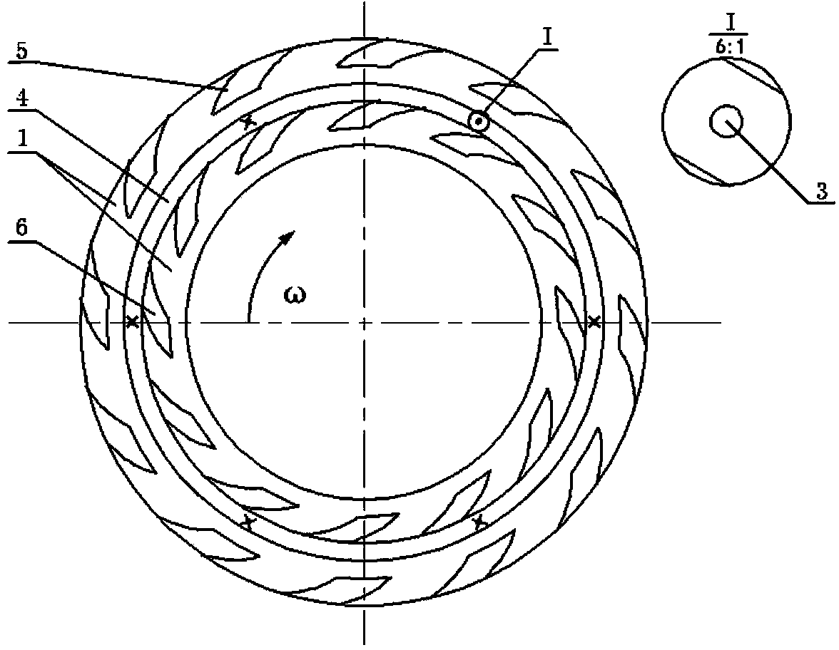
[0027] refer to figure 2 , this embodiment is a common occasion.

[0028] The outer dynamic pressure groove 5 is arranged on the outermost side of the static ring 1, and there is a dam area between it and the annular groove 4; the inner dynamic pressure groove 6 is arranged inside the annular groove 4 and communicates with the annular groove 4; the reverse flow pump on the outer side The dynamic pressure groove 5 can reduce the flow of the externally applied fluid to the outside of the seal, and the downstream pumping dynamic pressure groove 6 on the inside can increase the flow of the externally applied fluid to the inside of the seal. By separately controlling the flow of the externally applied fluid to the inside of the seal The amount of leakage on the outside, and then effectively control the leakage of the actual sealing medium inside the seal to the outside of the seal.

Embodiment 2

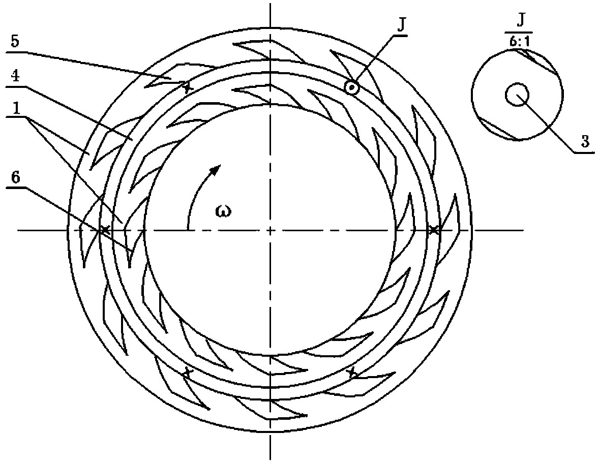
[0030] refer to image 3 The difference between this embodiment and Embodiment 1 is that the outer dynamic pressure groove 5 is distributed on the outside of the annular groove 4 and communicates with the annular groove 4, and the inner dynamic pressure groove 6 is distributed on the inner diameter side of the static ring 1 and connected with the annular groove 4. There is a dam area between the grooves 4; the outer downstream pumping dynamic pressure groove 6 can increase the flow of the externally applied fluid to the outer side of the seal, and the inner countercurrent pumping dynamic pressure groove 5 can reduce the flow of the externally applied fluid to the outside of the seal. The role of the flow inside the seal is to control the leakage of the externally applied fluid to the inside and outside of the seal respectively, thereby effectively controlling the leakage of the actual sealing medium on the outside of the seal to the inside of the seal. The rest of the structur...


PUM


Abstract

The invention discloses a direct and reverse flow pumping combined radial double-end-surface mechanical sealing device which comprises sealing movable rings capable of rotating along shafts. Fixed rings which are flexibly fixed to sealing cavities are used as compensation rings; external liquid pressure lead-in channels are arranged in the fixed rings and are peripherally uniformly distributed in the fixed rings; annular grooves are formed in the end surfaces of the fixed rings 1, and small holes which are communicated with the channels are formed in the annular grooves; outer-side dynamic pressure grooves and inner-side dynamic pressure grooves are formed in two sides of each annular groove, and dynamic pressure effects can be realized by the outer-side dynamic pressure grooves and the inner-side dynamic pressure grooves; direct and reverse flow pumping effects can be respectively realized by inputted external liquid on the outer-side dynamic pressure grooves and the inner-side dynamic pressure grooves relative to external liquid, and the inputted external liquid is inputted via the small holes, so that leakage rates of externally fed liquid on the inner and outer sides of the sealing rings can be respectively controlled, and leakage rates of sealing media can be reduced. The direct and reverse flow pumping combined radial double-end-surface mechanical sealing device has the advantages that leakage rates of sealing joint surfaces can be reduced by the aid of the direct and reverse flow pumping effects, and the direct and reverse flow pumping combined radial double-end-surface mechanical sealing device is applicable to places where sealing media can significantly affect environments.

Description

technical field [0001] The invention relates to a radial double-end mechanical seal device for a rotary fluid machine, in particular to a radial double-end mechanical seal device with different requirements for externally applied fluid on the inner and outer sides of the seal. Shaft end seals of various compressors, expanders, pumps, reactors and other rotating machinery. Background technique [0002] Radial double-end mechanical seals have been reported. For example, Chinese patent CN101158405A proposes a radial double-end mechanical seal device with compact structure and convenient application and installation. However, it only considers the static pressure effect caused by the externally applied pressure, and does not provide a feasible solution for the dynamic pressure effect. At the same time, the most important thing is that it lacks the consideration of separately controlling the leakage of the externally applied fluid on the inside and outside of the sealing ring, th...

Claims


Application Information

Patent Timeline
Patent Type & Authority Applications(China)
IPC IPC(8): F16J15/34
Inventor 刘向锋黄伟峰胡松涛宋智翔刘莹王玉明
Owner TSINGHUA UNIV
Why Eureka
Try Eureka